Years of experience and ceaseless experiment, together with the ever-widening science of engineering, have made the ship’s engines the marvel that they are today - powerful and reliable

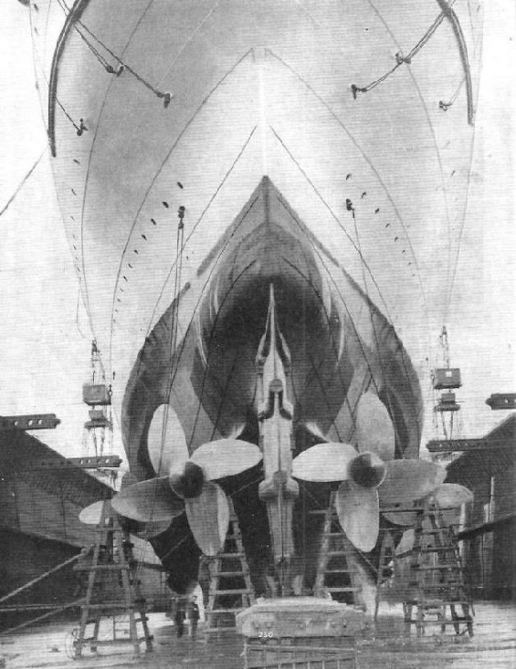
THE THRUST OF THE MODERN LINER’S MIGHTY ENGINES is transmitted to the water by screw propellers that operate in the water in much the same way as the ordinary mechanical screw turns in wood. The propellers thus push the vessel forward. The illustration shows the four-bladed screws of the famous RMS “Mauretania”. Over 70,000 hp was transmitted on these four screws and they drove the ship at a speed of over 26 knots. Each screw was driven by a separate steam turbine.
A QUARTER of a century ago the merchant fleets of the world were composed of steamers and sailing ships. To-day, sailing ships have become obsolete except for a few special purposes. Steamers have been reinforced by motor ships; but even so it is customary now to refer generally to all power-driven ships as steamers. This term covers a multitude of arrangements and a bewildering array of equipment. It recalls firemen, stripped to the waist, shovelling coal into white-hot furnaces. It gives a picture of big stokeholds with oil being fed into boiler fronts, of smooth turbines with their whining gear, and of pulsating rods and moving rocker arms of internal combustion engines. Finally, it calls to mind the electric dynamos and motors which provide the propelling force for the newest of all ships - the electric ship.
Whichever of these main types and variations is employed, the majority of modern power-driven ships have one feature in common - they are driven through the water by screw propellers. There is also the paddle, which is the oldest and, for certain purposes, the most useful form of propulsion. For special tugs, excursion ships and many shallow draft vessels it has few rivals.
The screw propeller, however, is used for most sea- and ocean-going vessels. Its action is that of a mechanical screw. Theoretically, each turn of the screw advances the ship a distance equal to the pitch, just as one turn of an ordinary carpenter’s screw advances it into a piece of wood a distance equivalent to the pitch. But, as wood is a solid, and water a fluid, it is not possible to imitate the motion exactly. When the marine screw revolves, the speed of its revolution has an effect upon the distance travelled. Because of the fluid nature of the medium in which the propeller is turning there is a “slip” for every revolution.
Almost all the fastest transatlantic liners, such as the “Queen Mary”, use four screws, and are referred to, therefore, as quadruple-screw steamships. Vessels such as the famous “Olympic” employed three screws, but two only did the work when the vessel was in harbour manoeuvring, the third, driven by a turbine, being employed at sea for giving extra power during the long ocean voyage. Twin screws are more generally employed in passenger-cargo and passenger liners of power up to about 30,000 hp. In cargo vessels a single screw is popular for power not exceeding about 4,000 hp. Other things being equal, the shipbuilder can offer the shipowner a cheaper hull if only one screw is used. Less space is occupied in the after part of the ship by tunnels in which the shafting runs.
The screw itself is attached to a tail-shaft. This enters the ship’s structure through a watertight aperture and is then coupled to the tunnel shaft, which is another length of shafting supported in bearings. This connects the propeller to a further portion of shafting in the engine-room itself, known as the thrust shaft, which, in turn, is coupled to the machinery. On the thrust shaft is a device against which the push of the screw is taken in propelling the ship. Just as it is necessary for an oarsman to brace his feet against a stretcher to give the necessary “kick” to his body, so a similar arrangement is needed for the push of the screw. This device is known as the thrust block. Forward of this block is the main propelling engine.
Here the shipowner’s difficulties begin. With all the bewildering array of fuels, engine types and arrangements available to-day, choice is difficult. The oldest, most tried and still generally most popular form of propulsion is an ordinary reciprocating engine. This is driven by steam generated by boilers. Such an engine is known as a compound-triple-, or quadruple-expansion engine, according to the number of cylinders it has. Steam is a gas under pressure, and can push down a piston only if allowed to expand.
A compound engine has a high-pressure and low-pressure cylinder. A triple-expansion engine has three expansions and a quadruple expansion engine has four expansions in cylinders of progressively increasing diameters, In each cylinder is a piston, with a piston rod. The piston rod is attached to a connecting rod by a cross-head, working in a guide, and the connecting rod is coupled to a crank that revolves and drives the propeller shaft. A given volume of steam is admitted by a valve to the space between the top of the cylinder and the underside of the cylinder head. The steam is then cut off from the supply and expands; the valve opens again and the steam exhausts. An identical operation takes place on the underside of the piston, and thus double-action is given. Reversing, as in an ordinary railway locomotive, is arranged by altering the valve motion.
This type of propelling machinery is essentially simple and reliable. It takes its energy from the boilers, which are mainly fired with Britain’s native fuel - coal. It drives many of the auxiliaries needed for operation - air pumps for creating a vacuum in the condenser, and hot well pumps and, sometimes in small ships such as trawlers, various auxiliaries for working the ship.
The air pump is necessary because of the condenser which converts the steam to water again. Unlike a locomotive, a ship, because of its long voyages, cannot afford continually to be taking fresh water on board and cannot “puff” the exhaust up a chimney. A few old tugs in New York Harbour are almost the only remaining vessels with non-condensing engines in existence. The condenser is a circular casing containing a nest of tubes, through which the steam passes, surrounded by cold salt water, which is kept in motion by a centrifugal pump. In some machinery spaces this particular pump is driven by a vertical reciprocating steam engine. In contrast, the four huge main circulating pumps in the Normandie are electrically driven, and each handles 7,000 tons of water an hour.
In the engine-room, say, of a small tramp, apart from the auxiliaries mentioned, there are generally an electric-lighting dynamo, pumps for pumping out the bilges, ballast tanks and holds, freshwater and sanitary pumps and a steering engine. Forward of the main machinery is the boiler-room, with the boilers flanked by coal bunkers, from which coal reaches the stokehold floor by gravity.
It was only a few years before the war of 1914-1918 that the turbine began to play any important part in propelling merchant ships, and then principally in passenger ships, where it was coupled direct to the propeller.
The turbine is a rotary machine and, as such, is quite different from the engine that we have been discussing above, which is reciprocating. The turbine is rotary in that it comprises two portions, one of which turns in the other. The stator, or stationary part, has fixed blades, and the rotor, or moving part, has corresponding blades arranged on “wheels” on the main shaft, which revolve in grooves in the stator.
When the steam enters under pressure it hits the fixed blades and “bounces off” on to the blades of the rotor wheels, which, collectively, it turns, thus causing the propeller shaft to turn also. After leaving the turbine the steam goes through the same process as in the reciprocating engine. It returns to the boiler by way of the condenser and a hot well. The hot well is a device for bringing the water to a point conveniently near boiling-point, so that the amount of energy required for evaporating the water to steam is thereby reduced.
Reduction Gear
The turbine differs from the reciprocating engine, in that it is not itself a reversible prime mover. A portion must, therefore, be incorporated in the turbine casing, in which the blades are set in the opposite direction, so that when steam is admitted to this part of the machine the shaft turns in the reverse direction. This is known as the astern turbine. For reasons of space, its size
can be only a fixed proportion of that of the ahead turbine. It is not practicable, therefore, with a turbine to have full power astern.
The turbine, because of its rotary nature, runs at high speed. It is not necessarily of benefit from the propulsive point of view for the turbine to be coupled directly to a propeller, for if the rate of revolutions is too high, the propeller “slips” idly round in the water, doing no useful work in thrusting the ship forward.
If the ship is fast and the hull is fine lined, high propeller speed, generally speaking, may be a matter of small importance; but cargo ships are fairly full bodied, and a slower running screw is necessary. When the turbine was adapted for cargo craft, it was necessary to introduce between the turbine and the shafting some form of reducing gear. Thus the propeller itself could turn at a number of revolutions suitable to the hull requirements, the reduction in some instances being from 6,000 to eighty revolutions a minute.

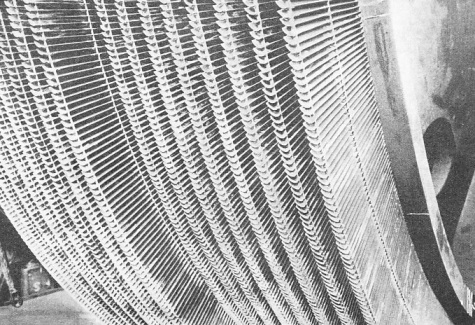
TURBINE BLADING is made of phosphor-bronze or stainless steel and is curved in section. The steam on entering the casing at the high pressure end impinges on the blades and gives the turbine wheel a rotary motion. The adjustment of the blading calls for minute care, since the clearances between the fixed blades and the moving blades are measured in thousandths of an inch.
Once it was appreciated that speed reduction could take place by means of a toothed pinion on the end of the turbine, meshing with a large gear wheel on the propeller shaft, it was possible to arrange two, or even three turbines round a common gear-wheel. It became possible to haye a triple-expansion turbine arrangement, similar to that of a reciprocating engine, and the best and most economical use could thus be made of the steam.
A turbine of large diameter can always use low-pressure steam. For that reason, the arrangement mentioned above as having been adopted in the “Olympic” proved successful for many years. The “Olympic” had quadruple-expansion reciprocating engines on her two outer shafts; but the steam from the low-pressure cylinder of each of these engines, instead of going to the condenser, was led into a large diameter low-pressure turbine on a centre shaft. It went afterwards to the condenser.
Another important type of machinery which is popular for certain types of ships is electric drive. The “Normandie”, one of the largest ships in the world, is electrically propelled. In this ship water-tube boilers supply steam to turbines of non-reversing type. These drive alternating-current generators which supply current to electric motors coupled to the propellers. At the same time, another battery of electric generators gives direct current for all the auxiliary services on the ship. In a vessel such as the “Normandie”, the current demands are very high.
Advantages of Electric Drive
One of the main advantages claimed for electric drive is that full power is available astern, since there are no astern turbines, and the electric motors can operate at full torque, as it is called, in either direction. The length of shafting is shorter, since the only connexion between the main prime-mover (the alternators and the propelling motors) is an electric cable. Control is also flexible, and the alinement of the main power-producing plant and of the electric motors themselves need not be rigid as with ordinary geared turbines.
A variation of the turbo-electric scheme is found in diesel-electric drive. This differs in several details, for the diesel engine is attached to generators which in turn supply current to propelling motors. But, for technical reasons, the diesels which drive generators, supplying propulsive power, generate current also for auxiliary power. In the turbo-electric scheme there are two groups of generators supplying alternating and direct current; with diesel-electric drive direct current can be used for all purposes, from lighting the ship to propelling her. It is possible, also, for direct-current propelling-motors to be controlled from the bridge ; but there again is the disadvantage of high first cost. It has been stated, also, that if too high powers are attempted with diesel-electrical propulsion, there may be vibration because of the high revolutions, and risk of the reciprocating parts of the diesels coming into synchronization from time to time.

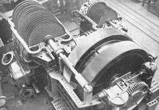
GEARED TURBINES are the most compact type of prime mover for ship propulsion. The stator with its fixed blades and the rotor with its moving blades are contained, as explained in the text, in casings. This view shows the tops of the casings removed and the high-pressure and low-pressure turbines with their respective gear pinions meshing with the main gear wheel. The particular set illustrated is intended for driving a large passenger and cargo liner and has an output of about 8,090 shp.
The diesel system has been successfully employed, however, in a variety of ships of 3,000 hp downwards, including one particularly interesting group of oil tankers. Here the control to the main propelling motor is embodied on the bridge in a pedestal which contains also the controls for automatic gyro steering, or “Metal Mike”, as it is known. Thus, theoretically, the navigator can set the speed of his propelling motor by adjusting the handle on the pedestal. Her course having been set, the ship will run herself for as long as the controls are left untouched Diesel-electric drive has also been employed for tugs, where excessive manoeuvring is needed, and in ferries. It forms a useful means of reducing the high speed of the propeller motor.
Scotch boilers and water-tube boilers are the two principal methods by which steam is raised to be used in a turbine or reciprocating engine. A Scotch boiler is a fire-tube boiler - that is, the gases, when coal or oil is burnt, rise upwards from the combustion chamber via furnaces and pass through tubes which are surrounded by water. The heat taken from the tubes causes the water to boil and the steam to come off at the top of the boiler from the stop-valve. This type of boiler, which is the oldest and best tried in marine practice, is suited to low pressure - not more than 250 lb per sq in.
The steam leaves what is called the stop-valve at the top of the boiler either as saturated steam - that is, with a certain amount of water vapour still contained therein - or as dry, or superheated, steam. Superheated steam, before leaving the boiler, passes over a series of tubes in which there is a further amount of heat from the boiler. The last ounce of moisture is thus taken from the steam before it proceeds to the prime mover. This “dry” steam is better thermodynamically and is capable of much more efficient expansive working than ordinary saturated steam. It is, therefore, becoming increasingly popular in all classes of ships.
The water-tube boiler, which also employs superheating, uses air heaters in which the air for combustion is thoroughly heated before it is drawn into the boilers. The reverse process to that in the Scotch boilers takes place; in the water-tube boiler the water is in tubes. These are used to connect together drums in which the water is contained. The heating is underneath the tubes.
A simple example is afforded by a three-drum water-tube boiler, in which the drums themselves are fore and aft, the tubes being slightly curved. The two drums are at the bottom corners of an equilateral triangle, the top drum being that in which the steam is collected, finally to go to the prime mover from the stop-valve. They are flexible in the operating sense and steam can be raised quickly in them.
Water-tube boilers, because of their light weight, compactness, quickness of steam raising and flexibility are becoming increasingly popular for passenger-ship work. The pressures at which steam is now raised in these boilers are increasing, and it is common to find superheated steam being generated in them with oil firing at 350 lb per sq in or even higher.
The motor ship now forms an important part of the world’s mercantile marine. In her cylinders fuel is rapidly burned, as the explosion may be chemically termed. The explosive action caused by the burning forces the pistons down and, as in a steam reciprocating engine, turns a crank.
The internal combustion engine does the two operations in one action and in one place. Therefore, until fairly recently the oil engine (or diesel engine as it is sometimes generically, though incorrectly, called) has been smaller, power for power, than the steam plant. But advances in steam propulsion have been so swift that with modem turbine plant, and even with some reciprocating engine plant, there is little to choose between the rival methods in space taken up, first cost, or in complexity. The diesel engine is confined entirely to oil, although some of the original engines of this type were designed for burning powdered coal as a fuel.
B y comparing the first ocean-going motor ship of 1912, which could develop only 1,800 hp in sixteen cylinders, with the 3,000 hp which can now be developed in one cylinder, some idea may be obtained of the progress that marine engineering has made.
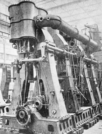
THE RECIPROCATING ENGINE has been the friend of the marine engineers for many years and is still used for propelling a large number of vessels. This picture shows the cylinders which, of increasing size, provide various stages of expansion for the steam. An engine of this type is capable of developing about 3,000 hp at 98 rpm and is the kind of machine employed for driving large cargo steamers.
You can read more on “How the Marine Turbine Works”, “Marine Engines and Their Story” and
“The Queen Mary’s Engines” on this website.


 y comparing the first ocean-