

© Shipping Wonders of the World 2012-

Navigational Charts
An immense amount of careful and skilled work goes into the making and revising of the various types of charts upon which mariners depend
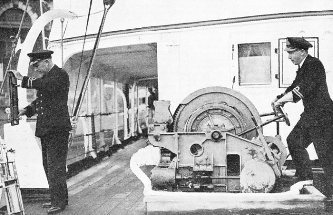
OCEANOGRAPHICAL OBSERVATION of every kind is carried out by H.M. survey ships to obtain data from which charts are drawn up. In HMS Challenger, for instance, special bottles (left) are carried to obtain samples of water and recordings of temperature from depths as great as 24,000 feet. A special type of winch is used for bringing these bottles and other oceanographical instruments to the surface. HMS Challenger, 1,140 tons displacement, has been doing valuable survey work since 1911.
THE first known map of the world, a Babylonian clay tablet of about the eighth century BC, depicts the ocean as being formed by two circles surrounding the land. In AD 150 Ptolemy produced a map that for 1,400 years was considered the “standard” for maps and was surprisingly correct in comparison with the distorted productions of later cartographers in the Middle Ages.
Martin Behaim’s map, in 1492, depicted the world on a globe, but according to this, if one sailed westward from Europe or Africa, the first land encountered would be the coast of China. America, which was then unknown, though on the point of discovery, was omitted entirely. From these crude beginnings mariners began to record their observations of the coasts and seas upon “sea-
The Hydrographic Department of the Admiralty owns a drawing on vellum of Dampier’s voyage to the East Indies and the drawings for Collins’s Great Britain’s Coasting Pilot, dated 1693, which is believed to contain the first charts printed in English.
By 1786 the East India Company had a collection of nearly 350 charts of England and the road to India and China, via the Cape. In 1796 the Hydro-
In a Gnomonic Chart an attempt is made to improve upon Mercator’s method by keeping the central meridian true north and south, while the meridians on either side incline towards the central meridian from the bottom towards the top. The best-
The types of charts issued include navigational charts, track charts and charts for Great Circle sailing, metero-
The sources of information required for the making of a chart include notes, sketches and surveys made by officers of navies and of the mercantile marine. Other sources are harbour authorities, special expeditions sent out for the purpose, Government surveys and -
The surveying branch of the Navy controls a number of survey ships. In 1936 the Endeavour was surveying East Indian waters, the Stork was in the Mediterranean, the Herald in Chinese waters and the Challenger in the West Indies. The Moresby, of the Royal Australian Navy, was surveying the Great Barrier Reef and the Beaufort, Fitzroy, Flinders and Kellett were engaged in British waters.
In compiling a new chart a suitable base on land is first fixed, a straight line that can be measured accurately. This is done on as flat ground as possible. Either end of the line must be marked by a conspicuous object and be visible from the other end. A short base is measured by a 100-
From the shore, or from boats working close in to it, every yard of the coast-
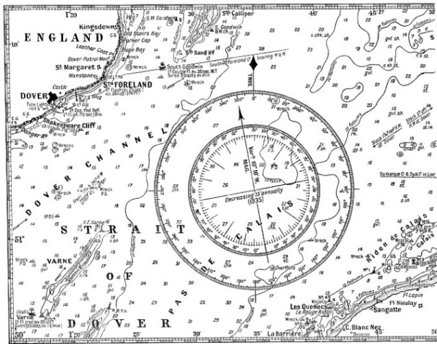
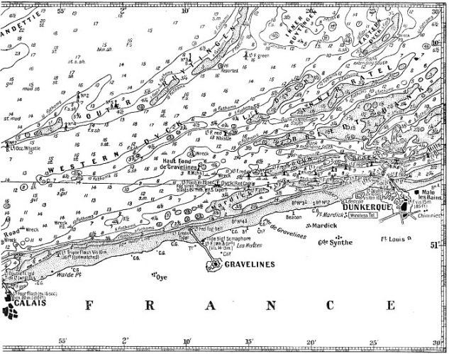
CHART OF THE STRAIT OF DOVER between Dover and Dunkerque (Dunkirk). A straight line drawn between these two ports crosses the course. A note on the chart states “Dunkerque Lt. and Dyck Lt. in Line”. This means that the vessel should keep these points in line to reach state of the tides, whose strength is marked with feathered arrows. From the Dyck Light to Dunkerque, the West Pass between the Snouw and constitute a danger to navigation, their position is shown by “wreck” buoys. Characteristics of lightships are noted on Western Dyck Sand, which shows depths of only 3 fathoms (18 feet) in places. A vessel drawing more than 18 feet, therefore, cannot take a direct port safely. The course, therefore, leads at first from Dover to the Dyck Light. Allowance must be made for compass deviation and for the Mardick Banks is marked by lines of black buoys to port and of red buoys to starboard. Wrecks are marked on the chart and, where they the chart such as “South Goodwin -
The operation of depth-
Observations of the tides and currents have to be made and the magnetic variation of the compass in the locality established. A rating constantly watches the tide level to ensure that the soundings, which are taken at every stage of the tide, can be reduced to a common level. The nature of the sea bottom has to be found by bringing up samples of it. This is done by “arming the lead”. A piece of tallow is fixed at the end of the sounding lead, so that a specimen of the “ground” will adhere to it when hauled up. Sketches of the coast’s outstanding features, as seen from the sea, have also to be made.
Eventually the rough draft of the new chart is forwarded to the Hydro-
A tracing of the original drawing is now made. The features are drawn in with coloured inks and the arrangement of the writing of names is given particular attention. Different styles of type are used to draw attention to rocks, shoals and other dangers.
Bold, plain type is used to mark under-
After months of laborious work, the tracing goes to the engraver. When proofs and corrections have been made, and several officers have scrutinized the work, it is ready for reproduction and issue.
The old method of engraving on a copper plate is still considered best, although lithography is largely used and even a combination of the two. Particularly delicate work is that of making corrections to existing plates. The printing is rarely done from the copper plate nowadays, an impression being taken off on a zinc surface and copies taken from this. All calculations are made to give accuracy to the nearest hundredth of an inch.
On a typical British Admiralty chart, the badge of the Hydrographic Department is shown above the title and near it the price. The sources from which the surveys were made are given, and then follows a statement of the magnetic variation and such notes as:
“All bearings are True and are given from seaward”;
“Soundings in Fathoms”;
“Reduced approximately to the level of Mean Low Water Springs.”
Different levels are taken according to the part of the world depicted. Allowance for the state of the tide has therefore to be made when using the chart.
On Mercator charts the scale of the chart is referred to a parallel of latitude running somewhere across the middle. On a small-
In the lower margin of the chart, the number of the chart is shown and also the dates of its various editions. A mass of small figures will also probably be seen -
When information is received from a source other than the Notices, necessitating a correction on the chart but not of sufficient importance to require its complete withdrawal, the year, month and day of the correction appear as follow -
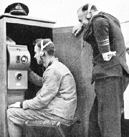
ECHO-
Latitude and longitude are marked, and the scale on the eastern and western boundaries of the charts corresponds with geog-
Tidal information is tabulated, showing the set and rate of the tide at various places, and also “H.W.F. & C.” (High water full and change.) This is a means of finding the time of high water at a given place. By multiplying the number of days since the last new or full moon (less two days in the region of the Thames estuary) by fifty minutes (the approximate daily variation in the time of the tides), and adding the result to the given time of “H.W.F. & C.”, the time of high water can approximately be found.
Information regarding lights and buoys is given. An entry such as: “Beachy Head -
Sketches are given of prominent objects and of lighthouses and beacons, so that they can be recognized by day. Wrecks are marked, often with the symbol P.D. against them, meaning “ Position doubtful”, or P.A., meaning “ Position approximate”.
Having found a position and the destination required, if on the same chart and not too far apart, the course to be steered can be ascertained by placing a parallel rule upon the line of the intended route, then referring the movable leg of the rule to the nearest compass rose and reading off from it the course to be followed, “true” and “magnetic”. Allowance must be made for the tide and currents, and the route will be examined for rocks, shoals or other obstacles.
Every inch of the sea bottom cannot be surveyed. The diameter of the lead used is only about 2-
In a chart on a scale of 6-
“Fathom lines” following contours of various depths, according to the scale of the chart, are a valuable guide in approaching a strange shore, and advise when precautions should be taken to look for hidden dangers. Buoys are liable to drift and get out of position. Too great reliance must not be put on them, and the ship’s position should be checked from stationary objects ashore rather than from a doubtful buoy.
The Notices to Mariners issued by the Admiralty are booklets giving information of alterations in lights and buoys, and notes of wrecks, of recently revealed dangers and of other matters affecting charts.
As a supplement to charts and Notices every vessel should carry the Sailing Directions of the part of the world to be visited. These books, some seventy in number, cover most of the globe and describe fully lights, buoys, weather, tides, currents, and local conditions, and give various information useful to the sailor. They, too, are kept up to date by Notices and Supplements.
A section of a chart is illustrated above. This chart would be used for a short trip from, say, Dover to Dunkerque (or Dunkirk).
If we draw a line with a ruler from Dover to Dunkerque, we see that the track takes us across the Western Dyck Sand, on which a depth at low water of only three fathoms in places is marked. If our ship drew more than 18 feet, therefore, at low water we might be in trouble. More three -
O n examining the chart we see a note “Dunkerque Lt. and Dyck Lt. in line”, and may take this as an indication that these two points, if kept one behind the other, will lead us safely into port. A pencil line drawn from the western entrance to Dover to the Dyck lightship takes us across a minimum depth of 5¼ fathoms at low water (31 feet), and as this will float a good-
ULTRA-
A convenient compass “rose” appears across our track and we can take our course from it. By placing one “leg” of our parallel ruler on our pencilled track and the other over the compass rose, we see that our course will be 98 degrees “True” or “South 72° East” magnetic. Further allowance will have to be made for the deviation of our own compass.
The state of the tides next demands attention. Several arrows are dotted about on the chart, with feathered tails, the number of “feathers” denoting the strength of the tide. Due allowance must be made for this, or we may find ourselves several miles east or west of our desired haven.
Once the voyage has started the dotted line outside Dover shows that we soon pass the ten-
If in doubt of our position, we might make a cast of the lead. We should expect to find a depth of twenty-
On the port hand we should expect to see the “ Lt. Occ. Whistle” (occulting light and whistle) black buoy at the foot of the Outer Ruytingen sand. About here the bottom is gravelly (“gvl.”) ; then come sand and pebbles. This soon changes to “st.” (stones) and we cross the Western Dyck Sand.
The French coast should be in sight now, unless it is misty. The Lightship is ahead. She has a “Red Cage” at her mast-
We now enter the West Pass between the Snouw and Mardick Banks. There is a sequence of black buoys to port and of red ones to starboard, with red and green lights respectively at night.
Along the shore are marked beacons, chimneys and church towers, to assist us in picking up our position and, if the weather be clear, Dunkerque is in view ahead. More detailed and enlarged particulars of the approaches to the port are given on this chart, to make the entrance still clearer. Given fine weather it is easy to find the way in. A number of wrecks will be noted near the fairway, but these are at a depth sufficient not to constitute dangers to navigation. Otherwise they would be marked by “wreck” buoys.
You can read more on “Instruments of Navigation”, “The Modern Ship’s Wireless” and “Romance of the Chronometer” this website.