

© Shipping Wonders of the World 2012-

How the Marine Turbine Works
The modern marine steam turbine has been developed from the two main principles, reaction type and impulse type, invented respectively by Hero of Alexandria about AD 50 and by Giovanni Branca in 1629
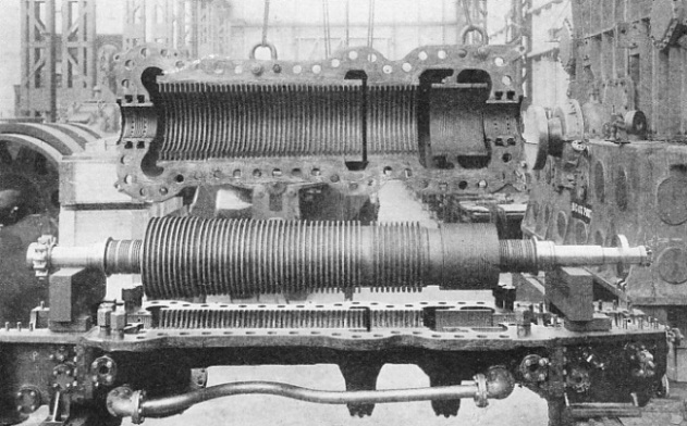
THOUSANDS OF BLADES are fitted to the rotor and to the casing of a steam turbine. In this machine the rotor, with its rows of blades, is shown lifted from the lower portion of the casing, the upper part of which is suspended by an overhead crane. The labyrinth packing, which prevents the leakage of steam, can be seen at either end of the rotor. On the left of the shaft is the coupling that transmits the drive, and at the right end of the shaft is the thrust collar.
THE smooth-
In the chapter ”Steam Turbine Engines” was traced the story of the turbine over a period of nearly two thousand years. We can now consider the action of the turbine, the reasons for the special shaping of the blades, the remarkable way in which the machine is kept steam-
Two distinct types of turbine were referred to in the earlier chapter. One was the “reaction” turbine invented by Hero of Alexandria about AD 50. The other type of turbine, suggested by Giovanni Branca in 1629, is known as the “impulse” type. It is important to distinguish between these two turbines because some modern machines are built on the reaction principle, and others are built to work as impulse turbines. Sometimes the two principles are adopted in one machine.
A firework, the well-
T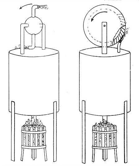 he first practical turbine was built at Gateshead, Co. Durham, in 1884. An early turbine of the impulse type was designed by Dr. C. Gustav P. de Laval in 1889. The impulse turbine depends for its action on the behaviour of steam (under pressure) that is allowed to expand. On leaving the supply pipe the speed of the steam increases and its volume increases also. At the same time the pressure falls. In the form of expansion aimed at and known technically as “adiabatic” expansion, no heat passes through the walls of the steam pipe. To permit the required expansion of the steam, without change of temperature, special nozzles are used.
REACTION AND IMPULSE principles are illustrated by these diagrams. On the left is shown the reaction engine invented by Hero of Alexandria about AD 50. On the right is the impulse machine designed by Giovanni Branca in 1629. The arrows indicate the
direction of rotation.
The steam, on beginning to expand, attains a speed that increases faster than does the volume. The pipe is therefore narrowed down, providing correspondingly less space for the volume of steam. These conditions apply only at the beginning of the
steam “blast”, but, after the initial rush, the volume increases faster than the speed of the steam. Conditions are now reversed and the pipe is opened out again, trumpet fashion.
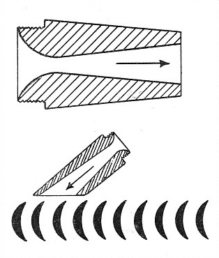
A pipe opening of this special shape, or nozzle, is used in de Laval’s impulse turbine and it is inclined, with other nozzles, at an angle of 19 degrees to the rim of a bladed wheel. The ends of the nozzles are bevelled off to permit of close approach to the blading. The blades are bucket-
The pressure change takes place only in the nozzles. The speed of the steam does, however, undergo a change in relation to the wheel. The steam enters the blades at great speed and loaves them slowly compared with the speed o! the wheel. It is this difference between the speed of entry and the speed of leaving that accounts for the work done in turning the wheel.
Technically described, the kinetic energy of the steam is communicated to the turbine rotor. In a de Laval impulse turbine the speed of the blades, about 30,000 revolutions a minute, must be nearly half that of the steam to achieve maximum efficiency. Such a speed, however, renders the single-
This arrangement of the turbine, with every wheel using part of the steam’s energy, is known as “velocity compounding”.
A second method of rendering the impulse turbine more efficient, especially for marine purposes, is the use of “pressure compounding”, as in the Rateau type of turbine. Where pressure compounding is adopted, the rings of fixed blades are omitted, and for them are substituted sets of nozzles which provide a drop in pressure with an increase of velocity.
The type of turbine that is more widely used than any other, especially for marine work, is the reaction turbine developed by the late Sir Charles Parsons. It was the invention of specially-
The Parsons machine, however, is not a purely reaction turbine as was that invented by Hero some nineteen centuries ago. In the Parsons turbine, although it is described as being of the reaction type, the steam has an impulse action on the blading in addition to its use on the reaction principle.
The principal difference between the designs of the impulse and of the reaction types of turbine lies in the shape of the cross-
Reaction blading, however, differs from that used for impulse turbines in the shape of the section as well as in its arrangement on the rotor. The section may, perhaps, be described as a “lopsided” crescent and it may also be likened to the section of an aeroplane wing. The blades, instead of being placed on the rotor with the “horns” of the crescents in a fore-
The shape and angle of the blades -
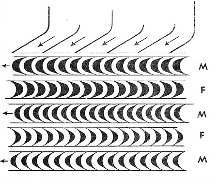
BLADES OF A VELOCITY COMPOUNDED TURBINE are arranged as shown diagrammatically. Steam enters the machine through the nozzles shown at the top in the direction of the oblique arrows, and impinges on the first row of moving blades (M) that move in the direction indicated by the horizontal arrows. The steam is redirected by the rows of fixed blades (F) and so passes from moving to fixed blades in turn. Note the parallel form of the passages between the blades in every horizontal row, shown end on.
The steam accordingly passes through the first ring of fixed blades or nozzles and, with an increase of velocity and decrease of pressure, imparts an impulse to the first ring of moving blades. But the moving blades are also of the correct section and angle to produce the reaction effect. The spaces between adjacent moving blades may be regarded as steam-
The Parsons reaction turbine is thus pressure-
Large numbers of blade rings are used in the Parsons turbine so that the number of “stages” in which the pressure falls shall be as many as possible. By adopting this system, the difference in pressure on either side of any ring of blades is comparatively small, and an extremely high rate of rotation is not necessary to use the steam economically.
In the de Laval impulse turbine the whole of the steam’s energy is expended on one row of blades, that is, in a single stage, and the speed of the rotor is consequently tremendously high.
Another outstanding feature of the Parsons turbine is the increase in size of the blades. Those at the low-
The increase in space between the rotor and the turbine casing, permitting of larger blades, provides also the necessary space for the expanding steam. The diameter of the rotor at the low-
 In ideal conditions the increases in size would be carried out gradually from one end of the turbine to the other; but, for convenience in construction, this is done in suitable steps or stages. For further convenience, the modern Parsons turbine is usually arranged in three separate “cylinders” or casings -
THE DE LAVAL NOZZLE is shown in detail in the top diagram. Steam passes, as indicated by the arrow, through a narrowing orifice and then through a trumpet-
The use of more than one turbine cylinder, which contains thousands of blades, may be compared with the expansive working of steam in the multiple cylinders of a marine reciprocating engine. The turbine, however, has many advantages over the reciprocating engine in its use of the steam. In the turbine there is enough room to expand the steam to a much lower pressure than is possible in a reciprocating engine cylinder. In addition, there is no alternate heating and cooling of the casing. The heat is conserved by lagging the casing with a covering of insulating material.
A further advantage in the turbine is the use of large exhaust passages which are always open to the condenser. The sizes of the exhaust ports and passage-
In these circumstances the surface condenser is of even greater importance to the turbine than to the reciprocating engine. The condenser enables useful work to be abstracted from the low-
Figures quoted by Professor E. N. da C. Andrade illustrate this point. He states that almost the same power can be obtained from steam at 200 lb expanded to ½-
These are the principles on which the modern turbine works, obeying natural laws and using the stored-
Centrifugal force may be demonstrated simply by the dropping of a match on a revolving gramophone disk. Immediately it touches the revolving surface the match flies off sideways. To prevent the turbine rotor blades from moving outwards similarly and jamming in the casing, an ingenious method is adopted to fix them.
Mechanical Stresses
In the rotor are cut a number of circular grooves of Ц-
When building up the complete rotor the blades are placed sideways in the Ц-
This system of end-
The low-
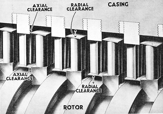
END-
The purpose of the sharp edge to the shrouding is twofold. It causes turbulence in any steam flowing round it and so serves as a baffle. Should the sharp edge accidentally touch an adjacent stationary surface, it is merely ground away harmlessly instead of jamming or causing friction by rubbing. Similar knife-
In the reciprocating engine steam is prevented from leaking from the cylinder through the piston rod opening by a “gland”. This gland is a circular box with a screw-
The labyrinth gland comprises a series of plain grooves in the rotor shaft. Rings project from the turbine casing into the rotor grooves and the interior of every ring is sharpened to a knife-
The clearances of the radial knife-
Little steam leaks past the knife-
In a turbine the bearings are exceptionally well fitted and are supplied with oil under pressure. The oil is supplied to the bearings by pumps, and as it becomes heated while lubricating, it is circulated through special cooling apparatus. The bearings are the only portions of a turbine that require oil, in striking contrast with the reciprocating engine, whether steam or diesel, on which all moving surfaces in contact must be lubricated. This clearly demonstrates why it is possible to use steam in a turbine at a pressure of 400 or even 550 lb superheated to a temperature of 750 degrees Fahrenheit. There is no oil in the turbine for this tremendous blast of hot gas to carbonize.
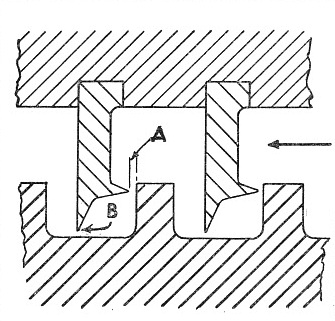
LABYRINTH PACKING to seal the turbine against the atmosphere is indicated here in section. At the top is part of the casing with protruding rings, having sharpened edges that revolve in grooves in the rotor. The adjustable axial clearance is indicated at A and the radial clearance at B. The direction of the steam flow in the turbine is shown by the arrow on the right.
Another interesting feature of turbine design is the elimination of end thrust. With steam rushing violently through the casing from one end to the other, the rotor is not only rotated; it would be pushed bodily forward as well if means were not adopted to prevent this.
In a set of turbine engines, the casings -
The end pressure on the blades is neutralized by the end pressure (in the opposite direction) on the dummy pistons. Dummy pistons are not always required, however. In some turbines steam is admitted at the centre of the casing and flows to either end simultaneously, so eliminating end thrust. The blading of such turbines is arranged at either end to face the central steam supply.
Another method of overcoming end thrust is to use a Michell thrust bearing on the shaft. The Michell bearing was patented by A. G. M. Michell in the years 1905-
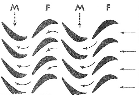
REACTION BLADING is illustrated by this diagram. The moving blades (M) revolve in the direction shown by the dotted arrows. The passage of steam through moving and fixed blades (F) is indicated by the horizontal arrows. The blades are in section, and their shape and the nozzle-
This action has the effect of drawing a wedge-
This wonderful device is also employed on either side of the collar used for adjusting the axial clearances of shrouding and labyrinths. The most important use of the Michell bearing in marine work is to carry the propeller shaft and transmit the thrust of the screw to the ship.
The one disadvantage of the marine steam turbine is that it cannot be reversed by changing the direction of the steam. This is overcome, however, by the use of a group of blading arranged for astern working which is attached to the rotor of one or more of the turbines comprising the “set”.
You can read more on “Propelling the Modern Ship”, “The Queen Mary’s Engines” and
“Steam Turbine Engines” on this website.