In a ship the size of the “Queen Mary” the propelling machinery and auxiliary plant attain enormous dimensions, yet so well has she been designed that her space and power are used to the fullest advantage

FOR THE MAIN MACHINERY SUPPLY SWITCHBOARD in the engine-room of the Queen Mary is the control point for the supply of electricity. The switchboard is 46 feet long. Leading down from the upper platform are the cage-protected feeders to the turbo-generators on the deck below. There are 735 miles of main insulated cable and 3,0JJ miles of subsidiary cable in the ship.
THE use of steam turbines and oil-fired boilers is considered to make for compactness. The machinery of the Queen Mary is compact, but the compactness can be disregarded from the outset. The power plant of this enormous ship is incredibly big, and it has to be big to drive so vast a buk - with a gross tonnage of 80,773 - through ocean rollers at a speed of over 30 knots.
The size of the Queen Mary is vividly demonstrated by the illustration on page 10. In a similar manner the vast proportions of her power plant may be visualized by bearing in mind that the greater part of the hull below the water-line is filled with machinery, packed in with the utmost skill that human ingenuity can devise.
Not a cubic foot of space is wasted. Right forward are the tanks for some of the water ballast and oil fuel as well as cargo and baggage spaces. Next are the water-softening plant and drinking water tanks. Then comes No. 1 boiler-room extending, as do all the machinery rooms, the full width of the ship, except for the oil-fuel tanks on either side. These tanks vary in width from 8 to 18 feet and line the sides of all the boiler-rooms and of the two electric turbo-generator compartments.
Farther aft are No. 2 boiler-room then the forward turbo-generator room, next Nos. 3 and 4 boiler-rooms, the after turbo- generator room and No. 5 boiler-room. Abaft No. 5 boiler-room are the forward and after engine-rooms, next the refrigerating machinery and finally the shaft tunnels, after-peak ballast tank and rudder, with the steering-gear above the level of the water-line.
The boiler installation of the Queen Mary was built by John Brown and Co, Ltd, at Clydebank (Dumbartonshire). In No. 1 boiler-room there are three double-ended boilers of the Scotch type described in the chapter beginning on page 958. These boilers are oil-fired and air is supplied to them through the ashpits on what is known as the closed-ashpit system of forced draught.
The air for combustion is heated in nests of tubes placed at each boiler end, and is forced into the ash-pits by a group of four 5-feet electrically driven fans. The Scotch boilers have twenty-four furnaces and the oil fuel is pumped in as a fine jet with a swirling action.
These boilers, with a working pressure of 250 lb, are used for auxiliary purposes in the ship, including the electric turbo-generators for the hotel services, the ship’s heating system, the laundry, swimming bath heaters, kitchen and galley auxiliaries and oil-fuel tank heaters.
Fuel oil is heavy and thick and has to be heated before being pumped to the boiler-rooms. The Scotch boilers have a diameter of 17 ft 6-in and a length of 22 feet. The eight corrugated furnaces are of 3 ft 7¾-in diameter. The exhaust gases from the furnaces in No. 1 boiler-room are taken up the fore part of the forward funnel, which accommodates also the uptakes from No. 2 boiler-room. In this room, over 66 feet long, are the first of the main water tube boilers.
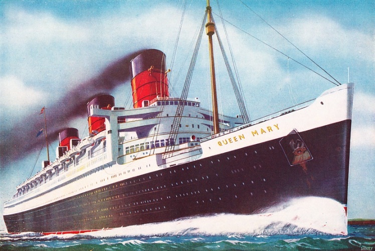
THE MIGHTY ATLANTIC RECORD BREAKER. Within little more than three months of her maiden voyage in May 1936, the Queen Mary had broken six Atlantic speed records, and had won the Blue Riband. On August 19, 1936, she left Southampton for New York and covered the distance from Bishop Rock to the Ambrose Light, 2,907 miles, in 4 days 27 minutes, at an average speed of 30·14 knots. She left New York on August 26 and covered the eastbound distance from the Ambrose Light to Bishop Rock, 2,939 miles, in 3 days 23 hours 57 minutes, at an average speed of 30·63 knots. Her speed records include the fastest day’s run eastbound and westbound, the fastest crossing in either direction and the fastest port-to-port times between Cherbourg and Southampton and vice versa. The illustration is by K M Sibley.
The Queen Mary’s main boilers are of the Yarrow type, and there are twenty-four of them, arranged in groups of six in four boiler-rooms. In each room the boilers are placed side by side in two groups of three running athwartships. The oil-fuel burners, seven to each boiler, are at the sides of the casings so that the firing alleyways run fore and aft. Each boiler has a steam drum 4 ft 6-in in diameter, connected by nests of steel tubing with three water drums, and a superheater drum, with its own nest of steel superheater tubes. All these drums are rolled forgings, each from a solid mass of steel; they are immensely strong, and are machined all over.
Arranged A-fashion above the steam drums are the tubular heaters for the supply of air to the furnaces. The furnace combustion air is supplied by thirty-two electrically-driven fans, eight in each main boiler-room. The fans in Nos. 2 and 3 boiler-rooms are of 5 ft 3-in diameter; those in Nos. 4 and 5 boiler-rooms are 3-in larger.
The air supply is on the closed-stokehold system of forced draught, in which every boiler-room is airtight. The air from the fans is forced through the heaters into the furnaces and thus aids combustion of the oil fuel. When working under forced draught the main boiler-rooms can be left or entered only through the doors of an air lock. In Nos. 2 and 3 boiler-rooms, where the hull tapers off forward, the boilers are slightly smaller than those in boiler-rooms 4 and 5. To balance this difference in capacity the boilers of Nos. 2 and 4 boiler-rooms work in conjunction and supply steam to the forward engine-room. The after engine-room is supplied by Nos. 3 and 5 boiler-rooms. Nos. 3 and 4 are served by the middle funnel and the furnaces of No. 5 exhaust into the after funnel.
Each main boiler is approximately 31 feet high, including the air heaters - roughly “as big as a house” - and the “street” in which they stand, with alleyways and thoroughfares, measures some 80 feet by nearly 270 feet. This space does not include the three great Scotch boilers in No. 1 boiler-room.
The working pressure of the main boilers is 425 lb per square inch, with steam superheated to a temperature of 700 degrees Fahrenheit. Steam at this temperature is an intensely hot gas, so that, instead of the analogy of houses in a township, the whole generating plant might be compared with a volcano in full blast.
Half-Mile of Steam Piping
There are some 2,600 feet of main steam piping in the Queen Mary. Piping for the ahead turbines has an internal diameter of 16-in and the astern pipes have a diameter of 12½-in. In the auxiliary steam pipe-line there are fifty-eight valves that reduce the pressure of the steam supply for special purposes other than the driving of the propelling turbines.
The stop valve on each boiler is fitted to the superheater outlet and is so designed that should a boiler tube burst, the valve operates to prevent any inflow from the main steam supply.
 A particularly interesting feature among the boiler fittings is the type of gauge used to indicate the level of the water. The forged steel body of the gauge is provided with two thick plate-glass covers protected from the steam by sheets of mica. The space between the glass plates is prismatic and at the back of the gauge are mounted strips of red and green glass, side by side.
TWO OF THE TURBINE CASINGS in the Queen Mary's after engine-room, next to their gear boxes the tops of which may be seen on the right of this photograph. The steam piping is heavily lagged with insulating material held in place by metal bands at intervals. Near the bend in the upper pipe is an air-diffuser of the ventilating system.
Behind these strips are four electric lamps, and their light, passing through the coloured strips, is directed by a lens on to the back of the steam and water space between the covers. Viewed from the front, the steam space appears red, and the water by reason of its bending action on light causes the green illumination to appear. Red and green thus provide a vivid contrast and indicate the water level where the two colours meet.
The illuminated gauges of a group of four boilers are brought to view at a single control point by the use of mirrors. In addition to these indicators there are devices that automatically shut off the fuel supply and sound an alarm whistle should the water fall to a dangerous level.
In addition to their steam generators, all five boiler-rooms contain auxiliary machinery for dealing with the supplies of oil and feed water. There are special devices for separating waste oil from the bilge water, electric oil-transfer pumps for handling the fuel from the tanks and additional boiler-feed steam pumps for emergency purposes.
Oil-Firing System
The 168 main oil burners are fed with fuel by a battery of twelve large oil-firing units. Each includes a strainer to ensure perfectly clean fuel, a necessary precaution because the burner orifice is only about the diameter of a small domestic pin. The pumping portion of the unit is an electrically driven rotary pump and, to enable the fuel to be pumped readily, it is steam heated. The burners can be lighted or extinguished with rather less fuss than a household gas cooker and they are fitted with a safety device that prevents withdrawal from the furnace front until the supply of oil fuel has been completely cut off. The oil fuel supply system in No. 1 (auxiliary) boiler-room comprises two units, one electric, the other steam-driven. An electric heater is provided for raising steam from cold.
A number of revolving steel wire brushes on flexible shafts 26 feet long, operated electrically, are provided for boiler cleaning. In Nos. 1, 3 and 5 boiler-rooms are installed two electric hoists for the disposal of ash and refuse.
The two turbo-generator rooms are situated forward and aft of the boiler rooms. There are seven British Thomson-Houston turbo-generator sets in the Queen Mary, with a combined normal output of 9,100 kilowatts - sufficient electrical supply for a town of over 100,000 inhabitants. Three of the turbo-generators are in the forward generator room, placed side by side in a fore-and-aft direction. These turbo-generators supply current for the hotel services - lighting, heating, cooking, lifts, fans, kitchen machinery and so forth.
Alongside the generators in this compartment are auxiliaries to hotel services boiler plant as well as air compressors and ballast pumps.
The hotel service turbo-generators are required not only at sea but also in port when the main boilers are shut down. The generators are consequently supplied with steam from the auxiliary boilers in No. 1 boiler-room, at a pressure of 230 lb super-heated to 650 degrees Fahrenheit.
 In the after turbo-generator room are four sets that supply current for the auxiliaries in connexion with the main propelling machinery, including forced draught fans and the vast array of electric pumps for lubrication, ventilation, condenser circulation and the handling of fuel oil, bilge and ballast. The four main turbo-generator sets are supplied with steam from the Yarrow boilers, through reducing valves, at 370 lb with a superheat to 680 degrees Fahrenheit.
THE GIANT EXHAUST TRUNKING from one of the low-pressure turbines may be seen above behind an upright girder in the Queen Mary’s main engine-room. In the background is one of the condensers and in the foreground are the tops of some of the turbine gear boxes. Each main condenser contains 41,000 square feet of cooling surface.
Each of the turbo-generators supplies direct current at 225 volts with an output of 1,300 kilowatts and comprises a 10-stage turbine running at 5,000 revolutions- a minute, geared to the electric generator running at 600 revolutions a minute. Every set is self-contained and the condenser is integral with the turbine.
In addition to the turbo-generators there are two 75-kilowatts emergency dynamo sots driven by Parsons eight-cylinder kerosene engines. The emergency power station is accommodated at the after end of the vessel on C Deck.
All the telephones, electric bells, lond speakers, fire alarms and similar apparatus in the Queen Mary are supplied with low-voltage power by two motor generators, each of 2 kilowatts capacity, and by a group of storage batteries.
The distribution of electric power throughout the ship proved a tremendous undertaking. There are 735 miles of main insulated cable and another 3,000 miles of subsidiary cable. The main machinery supply switchboard in the after turbo-generator room is 46 feet long. The switchboard in the forward generator room, supplying the hotel services, has a length of 37 feet. In addition to the main switchboards there are thirty-eight auxiliary switchboards and one for use in emergency. The extent to which electricity is used for power purposes in the Queen Mary may be judged from the fact that there are on board 578 electric motors, totalling 17,818 horse-power.
The motors that drive the winches and capstans alone aggregate 2,000 horse-power. Many of the special-purpose motors are of large proportions. The two that drive the anchor windlass are of 292 horse-power. Three large electric motors, each of 250 horse-power, are incorporated in the electro-hydraulic steering gear. The boiler rooms also absorb a considerable amount of electric power. The forced draught fans are driven by motors totalling 3,000 horsepower.
It is in the two great engine-rooms, however, that the real might of the Queen Mary is concentrated; and the enormous power is developed by engines whose working principle was discovered nineteen centuries ago. In the forward engine-room are the turbines that drive the wing shafts and in the after engine-room are those for the inboard shafts. The space occupied by the main engines is approximately 150 feet long, 110 feet wide and 40 feet high. The four main turbine sets in the Queen Mary are of the impulse-reaction type (see pages 787-791 and 1087-1091).
Each set has one high-pressure, two intermediate-pressure, and one low-pressure turbines, the shaft pinions of which engage with a main gear wheel. For working astern a high-pressure astern turbine is built into the second intermediate casing and a low-pressure astern turbine is incorporated with the low-pressure ahead turbine. The high-and first intermediate- pressure turbines are placed at one end of the gear-casing and the second intermediate- and low-pressure turbines at the other end.
The low-pressure ahead turbines are arranged on the two-flow principle with the steam inlet at the centre so that the end thrust is equalized without the use of the dummy pistons required for the single-flow machines.
1,024 Feet of Propeller Shafting
Each of the iron centres of the main reduction gear wheels was cast in one pieee and weighs 51½ tons. The cast iron lower half of the gear case for each of these huge wheels weighs 54½ tons.
The overall length of each set of turbines, including the Michell bearings that take the enormous thrust of the propeller, is 70 feet. The total length of propeller shafting that transmits the power of the Queen Mary’s engines to the giant screws is 1,024 feet.
 Each set of turbines can be operated as an independent unit. In addition, the high- and first intermediate-pressure ahead turbines can be isolated. Steam is then supplied direct to the second intermediate-pressure ahead turbine and, if necessary, the low-pressure turbine can also be isolated and the exhaust taken direct to the condenser.
DISTRIBUTION CABLES are held in special clamps bolted to the deck above. These cables carry electric current from one of the Queen Mary's auxiliary switchboards, of which there are thirty-nine. To the left is a group of knife-switches, with their insulated handles.
The important “axial clearance” of the blades is adjustable in conjunction with an electric fore-and-aft movement indicator and an alarm that, gives warning of any excessive end play of the rotor. This indicator is attached to the forward end of the emergency governor attached to each turbine. These governors automatically cut off the main steam supply should the speed become excessive through sudden variation in load.
The turbines are thus guarded against damage in the event of shaft fracture, loss of a propeller or other emergency. Steam is also shut off automatically should the forced lubrication system fail or cease to function satisfactorily.
Another interesting point arises in connexion with the huge helical reduction gears. In each instance, these are double, to equalize the end thrusts ol the helices and, to ensure resiliency, the pinions are hollow and attached to their shaft at the end farthest from the turbine. The internal pinion shaft is driven by the turbine rotor through a flexible coupling.
In the Queen Mary there are four main condensers, one for each set of engines. The condensers are 28 feet high, nearly 20 feet wide and over 20 feet long. Each condenser comprises a huge casing, similar to a ventilating cowl in general appearance with the opening turned inboard, and containing two separate nests of horizontal tubes. The central lane between the two set? of tubes permits the passage of exhaust steam to the bottom of the condenser, where it mixes with and heats the condensate in the storage reservoir.
Mammoth Condensers
There are in each condenser 13,780 tubes of copper-nickel alloy. The tubes are 15 ft 6-in long and of ¾-in diameter. Each condenser contains 41,000 square feet of cooling surface and can maintain a vacuum of 29-in of mercury.
Part of the tube space provides a pocket for the air which is extracted from the condenser by air-ejectors operated by steam jets.
The circulating pumps that force the cooling sea water through the condenser tubes are of the vertical type with the pump at the foot and the powerful electric driving motor at the top. There are eight of these pumps and they stand 12 ft 6-in high.
Special arrangements are made to maintain a constant supply of boiler feed water from the condensers by adding to or taking from the condensate. The feed water is extracted from the condensers by eight powerful electric pumps, each of which is capable of dealing with 550,000 lb of water every hour.
 After having left the electric extractor pumps the boiler feed water is passed through apparatus known as ejector coolers, with the dual function of cooling the condenser air-ejector’s vapour and heating the feed water. Next the feed water passes through another set of dual-purpose apparatus known as drain coolers, that heat the teed still further but cool the condensate or “drains” from the main feed water heaters.
A LOW-PRESSURE TURBINE in the after engine-room of the Queen Mary. In the background is one of the gear boxes. The turbines in the after engine-room drive the inboard propeller shafts and those in the forward engine-room the wing shafts. Each of the four sets of turbines consists of one high-pressure, two intermediate-pressure and one low-pressure turbines, the shaft pinions of which engage with a main gear wheel.
These feed water heaters are arranged in sets of four, working in three stages - low-pressure, intermediate- and high-pressure - taking steam from various convenient sources, including part of the bled steam from the main turbines. It will be appreciated that in heating the feed water some of the steam is condensed - hence the “drains”. The heaters are connected to the suction side of the turbo-feed pumps which deliver water to the main boilers at a final temperature of 370 degrees Fahrenheit. It is this inter-relation of heating and cooling devices that makes possible the wonderful efficiency of the Queen Mary’s vast power plant. The utmost possible value is extracted from every drop of fuel oil burnt in the furnaces. Every precaution known to science is taken to ensure that this efficiency shall be maintained. In every boiler the temperature of the furnace gases under the superheater is accurately measured by an electric pyrometer that records the temperature on a dial. The percentage of carbon-dioxide gas in the boiler flues is recorded by special electrically operated instruments so that a watch may be maintained on combustion and oil or air pressure adjusted as necessary.
Boiler and air heater tubes are kept clean by steam-operated soot blowers and all boiler casings are lined with firebrick. There are about 500 tons of firebrick in the boiler rooms of the Queen Mary. In addition to firebrick, vast quantities of insulating material cover exposed surfaces such as boiler casings, steam pipes, valves, heaters and apparatus of all kinds. No heat is allowed to run to waste.
It is not possible to catalogue all the auxiliaries and fittings in the engine-room of this great ship. There are water pumps, lubricating oil pumps and oil purifiers, torsionmeters that measure the twisting strain on the propeller shafts when under load, shaft and turbine revolution counters and recorders, drinking water pumps, oil coolers, pumps for sanitation purposes, electric fans and conditioning plant for the supply of air to parts of the ship.
Included in the machinery and equipment of the Queen Mary are a number of interesting and ingenious devices devoted to maintaining the safety of the great ship, her passengers and crew. The subdivision of the vessel into watertight compartments has been thoroughly carried out and the bulkhead doors can be closed by machinery. The doors are built to slide in grooved framework attached to the bulkheads and vary in size from those that will permit of a man’s passing through them to openings large enough to provide a passage-way for small motor-cars.
The watertight door system is divided into two sections, one comprising the doors in the lower part of the ship, the other including those in the passenger accommodation spaces. The sections muv be operated independently or simultaneously and the doors are closed within one minute from a central control on the navigating bridge.
Heard All Over the World
The doors are operated by hydraulic cylinders supplied with fluid at a pressure of 700 lb by two powerful steam pumps. The pumps are connected with the doors by about two miles of copper tubing. A bell fitted to each door gives warning seven seconds before closing begins.
Steering a ship of the Queen Mary a enormous size calls for the use of really robust equipment. The steering gear that serves the vessel weighs 180 tons and occupies a space about 68 feet long and 25 feet wide. The rudder stock (weighing with its frame 110 tons) comes up through the deck of the steering flat and is fitted with a massive steel yoke 15 feet long.
On either side of the rudder stock, arranged in pairs fore and aft, are four hydraulic cylinders mounted in a massive frame. The steel rams of opposed cylinders unite, on either side of the rudder stock, in massive bearings that encircle the ends of the yoke. Fluid under pressure is delivered to the cylinders by pumps driven by three 250 horse-power electric motors. The rams are forced in or out, according to the control exercised by the pumps and valve gear, and so the yoke moves with the rams, and swings the rudder to port or starboard as required.
The electric pump motors are arranged side by side forward of the operating rams and farther forward is the servo-telemotor unit, which enables control to be exercised from the wheel house or docking bridge. The huge steering machine is so sensitive that the movement of the navigator’s wheel by only one spoke is sufficient to put the helm over by a corresponding amount. Apart from the servo control, however, the helm can be put over by the action of the gyro-compass, the wonderful “iron mike” that electrically controls the pump motors and through them the movements of the great rudder.
I n addition to the use ot servo gear and gyro-compass control, the pump valves may also be operated by a hand wheel. As the whole apparatus is in duplicate the steering gear can thus be operated by six different wheels.
A MANY-BLADED ROTOR for one of the Queen Mary's low-pressure turbines undergoing final adjustments in the works of the builders, John Brown and Co, Ltd. There are sixteen ahead and eight astern main turbines in the Queen Mary.
In conclusion, there are three steam-using units on board the Queen Mary that cannot be ignored, and they must have been heard, by radio, all over the world. These are the enormous steam whistles, each 6 ft 7-in long with a diaphragm of 22½-in. diameter and weighing one ton. Electrically controlled, these whistles provide a note that can be heard for many miles.
You can read more on The R.M.S. Queen Mary - Super-liner and Where the Queen Mary was Built on this website.
You can read more about “Making Giant Propellers” for the Queen Mary in Wonders of World Engineering


