Rapid progress was made in the development of steam propulsion in the first half of the nineteenth century, and many features of great importance to-day were then introduced
MARINE ENGINES AND THEIR STORY - 2
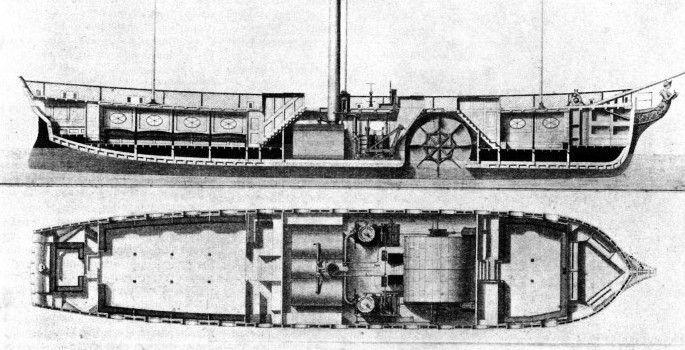
LONDON TO MARGATE IN 1818. Paddle steamers still voyage up and down the Thames, but one of the first vessels to ply on this service was the London Engineer, shown here in section. The picture illustrates the cabins fore and aft and the boilers and engines amidships. The paddle-wheel revolved in an air-tight casing in the hull and was driven by a pair of single cylinder bell-crank engines. The London Engineer was of 315 tons (builder’s measurement), with a length of 120 feet, a breadth of 24 feet and a draught of 5 feet.
FOLLOWING the introduction of paddle steamers on the Clyde and on the rivers of America and Europe, the Thames in due course received attention. In 1818 a wooden steamship was built for voyages between London and Margate. Thousands of Londoners and others have journeyed from the City to Margate by paddle steamer since these early days, long before the railways, and three years after Wellington’s victory on the field of Waterloo.
The London Engineer was constructed by Brent of Rotherhithe, and her engines were by Maudslay, Sons and Field. This vessel was 120 feet in length, 21 feet wide, draught 5 feet. By builder’s measurements her tonnage was 315. The engines, of the bell-crank type, had two vertical cylinders 36 in. diameter by 30 in. stroke. These cylinders drove cranks at either end of a shaft carrying two paddle-wheels. The paddle-wheels, 12 ft. 6 in. diameter and 6 ft. 6 in. wide, were fitted with eight radial arms carrying floats and made twenty-eight revolutions a minute. The arrangement of the paddle-wheels was of interest, as the shaft was only slightly above the water-line. In an attempt to overcome this difficulty the paddle wheels were placed in a casing amidships. The casing was airtight, but open at the bottom, and the floats projected below to keel level. Two compressing pumps were used to force air into the casing and so lower the level of the water in it. Unfortunately the action of the paddles drove away the air through the water, which thus rose in the casing and interfered with the propulsion of the vessel.
We have seen, in the previous chapter, the development of the steamboat from its first introduction to the general adoption, about 1820, of the side-wheel paddle steamer.
During this period, the firm of Boulton and Watt introduced the side-lever engine that remained as a standard type until after 1860. Side-lever engines were installed in the Cunard Company’s Scotia of 1862, the last and the best paddle steamer built for the Atlantic crossing. The two cylinders of the Scotia, each 8 ft. 4 in. diameter with a stroke of 12 feet, were supplied with steam at 20 lb. pressure by eight tubular boilers. The engines, developing 4,900 h.p., drove paddle-wheels of 40 feet diameter with floats 11 ft. 6 in. by 2 feet. Side-lever engines of such power and size make an interesting contrast with those of this type built earlier in the nineteenth century. Among the early side-lever engines, as introduced by Boulton and Watt, were those fitted to the paddle steamer Dee, one of the first mail ships to be driven by steam. A fine model, said to have been made by Henry Maudslay, representing the Dee’s engines, may be seen in the South Kensington Science Museum.
The original engines had cylinders 4 ft. 6 in. diameter, with a stroke of 5 feet, supplied with steam at a pressure of 8 lb. from tubular boilers. These engines drove 20-ft. paddle-wheels that gave a speed of eight knots.
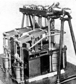 The pivoted beam was arranged to keep the engine’s centre of gravity as low as possible and to save head room. It was the custom in those early days of steam to ornament the large stationary engines on land, and the extension of the practice to marine machinery is demonstrated in the model by Gothic framing supporting the paddle shaft.
H.M.S. Gorgon, a steam frigate of 1837, was equipped with direct-acting engines of the type illustrated by this model. The cylinders, 5 ft. 4 in. diameter by 5 ft. 6 in. stroke, were placed directly below the crankshaft, and the piston rods were guided by the rods and levers shown. On the left of the engines are the air and boiler feed pumps attached to the condenser casings. H.M.S. Gorgon was of 1,111 tons, with a length of 178 feet and a breadth of 37 ft. 6 in; her speed was nearly ten knots.
Much of the credit for the development of the side-lever engine must be accorded to the engineer Robert Napier. His first marine engine, of the side-lever type, was built in his works at Camlachie, Glasgow, in 1824, and was installed in the paddle steamer Leven.
This river steamer, built at Dumbarton, Napier’s birthplace, was one of the first to ply between that town and Glasgow. The engine has a single cylinder of 2 ft. 7½ in. diameter and 3 feet stroke, and it is now preserved at the pierhead in Dumbarton. Robert Napier’s practice before 1845 was to employ two cylinders driving cranks set at right angles. This arrangement ensured an even turning movement of the paddle shaft and facilitated starting. An interesting property of the side-lever engine, however, was that even with a single cylinder, it could be started from its “dead” centre with the piston at either end of its stroke. Typical side-lever marine engines by Napier had two cylinders of 5 feet diameter and 6 feet stroke driving a pair of 24-ft. paddle wheels at 16 revolutions a minute. The boiler pressure was generally about 15 lb. per sq. in., giving approximately 700 h.p. Condensers were of the type where the incoming steam was met by a jet of cold water, and a partial vacuum was maintained by vertical single-acting air pumps. The vertical piston rods were guided by a modified form of the famous “parallel motion” invented by James Watt. This arrangement of rods and connecting links enabled the straight line movement of the piston rods to be transmitted to the beam of a land engine without the use of crossheads or guides.
In 1840 Napier’s side-lever engines were fitted to the four sister ships Britannia, Acadia, Caledonia and Columbia that formed the nucleus of the Cunard fleet. The Britannia left England on July 4, 1840, bound for Boston, and was the first steamer to carry mails to America. The voyage was accomplished in 14 days 8 hours at an average speed of 8½ knots, with a coal consumption of 38 tons a day. The engines of the Britannia and her sister ships each comprised a pair of cylinders 6 ft. ½-in. diameter by 6 ft. 10 in. stroke, giving 740 h.p. at 16 revolutions a minute. The Britannia was of 1,156 tons with a length of 207 feet, a breadth of 34 ft. 4 in., and a depth of 24 ft. 4 in.
Among other interesting side-lever engines of this period were those fitted to the paddle steamer Ruby, built in 1836 by Wallis, of Blackwall, for service on the Thames between London and Gravesend. The Ruby had a speed of 11¾ knots, which was about ¾ knot faster than any other paddle steamer on the river at that time.
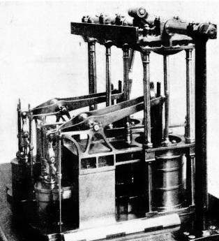 The engines of the Ruby, built by Seaward and Co., consisted of two cylinders 3 ft. 4 in. diameter by 3 ft. 6 in. stroke. Steam was supplied by flue boilers at a pressure of 3½ lb. The engines developed 100 h.p. and drove a pair of paddle-wheels 17 ft. 6 in. diameter, fitted with floats 9 ft. 1¼ in. wide and 1 ft. 3 in. Deep.
OPEN-TOPPED CYLINDERS, as represented by this model, were introduced in 1839, to overcome the difficulties caused by the use of the short connecting rods of the Gorgon engines shown above. Steam was supplied at 8 lb. per square inch, and the working stroke was obtained by the pressure of the atmosphere acting on the exposed piston tops. Engines of this type, but with three cylinders, were installed in the paddle steamer Sapphire. This vessel, built of iron in 1842, was 150 feet long and her 16-ft. paddle-wheels made thirty revolutions a minute.
The engines, in common with most side-lever engines, were efficient in operation but were excessively heavy and occupied a large proportion of the ship’s available space. The engines of the Ruby required a space 18 feet long, with an additional 24 feet for the boilers. The machinery and boilers thus occupied 42 feet of a length amounting to only 155 feet. The breadth of the Ruby was 19 feet, with a depth of 10 ft. 1 in. Displacement was 170 tons. An interesting method was employed in the construction of this ship. No frames were used and the hull comprised three, layers of planking, crossing each other and nailed together with felt between the layers.
Many attempts were made to reduce the space required in a ship by the side-lever engine. One method was to place the cylinders in a fore-and-aft position instead of athwartships. One cylinder was set directly under the paddle shaft, the piston driving the crank by side rods. The other cylinder was placed fore or aft of the crankshaft, which it drove through side-levers.
This compromise gave place to the direct-acting marine engine in which the cylinders were placed directly below the paddle shaft, driving the cranks by connecting rods. The first set of engines of this tyrpe was installed in H.M.S. Gorgon, a steam frigate designed by Sir W. Symonds and launched at Pembroke (Wales) in 1837. The engines were built by Seaward and Co; their design provided a great saving of weight, in addition to economy in space. The most important weight-saving improvement was the replacement of the usual cast-iron frames by wrought-iron columns to support the crankshaft and its bearings or entablature.
The two cylinders were of 5 ft. 4 in. diameter with a stroke of 5 ft. 6 in., and were carried on foundation plates each weighing 10 tons. These plates contained also a condenser and hot-well and supported the air and boiler feed pumps. The piston rods were guided by a special form of parallel motion from which the pumps were driven. The eight columns that supported the entablature were 7 in. diameter. The engines of H.M.S. Gorgon weighed 60 tons fewer than side-lever engines of the same power.
Steam was supplied by four tubular boilers. There were twelve furnaces fed with coal from two stokeholds. The coal bunkers, holding 400 tons, were arranged round the machinery, so affording a protection some 8 feet in thickness. The engines gave a speed of 9| knots on a fuel consumption of one ton of Welsh coal an hour. The Gorgon, of 1,111 tons, was built of teak with oak main beams and measured 178 feet in length, 37 ft. 6 in. in breadth and 23 feet in depth. The paddle wheels were 27 feet in diameter.
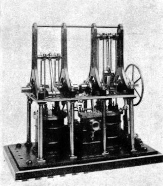
“STEEPLE” ENGINES were at one time popular in paddle steamers. Their design effected economy in space and permitted the use of long connecting rods. These engines acquired their name from the “steeple” appearance of the guides projecting above the deck. This model, in the Science Museum, South Kensington, was formerly used for propelling a small boat and has cylinders 41 in. diameter by 5⅓ in. stroke. Each piston has four rods attached to a crosshead from which the connecting rod extends downwards to the crankshaft.
H.M.S. Gorgon was one of the first steam warships in action and in 1840, with three paddle sloops, Vesuvius, Stromboli and Phoenix, she took part in the bombardment of Acre under Admiral Stopford. With a complement of 160 men she carried six guns on the upper deck, of which two were 10-in. guns and four thirty-pounders.
Although the engine arrangements of the Gorgon represented a definite improvement in space and weight, an objection raised against the design was the shortness of the connecting rods, imposing a heavy strain on the parallel motion guiding the piston rods.
To remedy this defect in marine machinery many expedients were tried, notably the open-topped cylinder, the oscillating cylinder, the “steeple” engine and the “return piston-rod”.
Open-topped cylinders for direct-acting marine engines were introduced by Seaward and Capel in 1839. The absence of top covers on the cylinders permitted attachment of long connecting rods close to the pistons. The connecting rods were forked at the lower ends to clear a light guide rod attached to the piston. The air and boiler feed pumps were worked from rocking levers actuated by links from the pistons.
One of the first sets of engines built to this design was installed in the paddle steamer Sapphire, an iron vessel built by Ditchburn and Mare in 1842. The Sapphire was 150 feet long and had a beam of 19 feet and a draught of 4 ft. 6 in. The three cylinders were arranged under the paddle shaft and were each 6 ft. 2 in. in diameter with a stroke of 3 feet. The steam pressure was only
8 lb. per square inch. Paddle-wheels were 16 feet diameter and turned at about thirty revolutions a minute. These engines were satisfactory in service and, as late as 1856, similar engines were used in the England-France Channel steamers Alliance and Havre.
Another arrangement of direct-acting cylinders was that proposed by Joseph Miller in 1841, and which effected a great saving in space. The cylinders were placed athwartships under the paddle shaft and the two air pumps were arranged between them. Surrounding the air pumps were the condensers to which the cylinders were bolted, thus providing a compact assembly that required no foundation plate. The cylinders were bolted down to the keelson of the ship. The cast-iron entablature carrying the crankshaft was supported by wrought-iron columns attached to the cylinders. Vertical slide bars were fixed to the cylinder covers to guide the piston rods, and the air-pump rods were guided in a similar manner. Long D-type slide valves were used, operated through rocking levers by eccentrics on the crankshaft. From one of the air-pump crank-pins, the feed and bilge pumps were worked by a bell-crank.
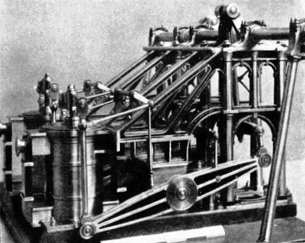
THIS FINE MODEL represents the engines of the paddle steamer Ruby, built in 1836 for service on the Thames between London and Gravesend. The engines were of the side-lever type, with two cylinders 3 ft. 4 in. diameter by 3 ft. 6 in. stroke. Steam was supplied at a pressure of only 31 lb. per sq. in, and the engines, driving 17 ft. 6 in. paddle-wheels, gave a speed of 11¾ knots. This was ¾ knot faster than any other Thames steamer of that day. The Ruby was 155 feet long, with a displacement of 170 tons.
“Steeple” engines took their name from the appearance of the piston-rod guides that projected some distance above the deck. This arrangement.was another device to obtain a long connecting rod, while retaining the cylinder’s position beneath the paddle shaft. Steeple engines were introduced in 1837 by G. Forrester and Co., of Liverpool, who installed one in the paddle steamer Rainbow. The piston rod of this engine was extended upward to form a kite-shaped loop accommodating the crank and connecting rod.
The next advance in steeple engine design was in 1839, when Joseph Maudslay and Joshua Field jointly patented a “return connecting-rod” engine. In this, the cylinders were placed vertically, but later an improved form of the arrangement was used extensively in a horizontal position, for driving screw propellers.
The piston of the Maudslay-Field engine was provided with two rods attached at the upper ends to a common crosshead with a connecting rod working downward on the crank. The piston rods were on the same side of the crankshaft, so that the timing of the strokes was imperfect and the arrangement fell into disuse. Several 70 h.p. engines were built, however, for paddle steamers on the river Rhone. These engines had cylinders 4 feet diameter by 3 feet stroke, and the air and feed pumps were worked from the crosshead by a beam. The steeple engine designed by David Napier of Millwall in 1842 showed an improvement in design by the use of four piston rods, two on either side of the crankshaft.
This arrangement enabled the cylinder and crankshaft to be lined-up, thus providing a satisfactory type of engine that became popular for steamers on the Clyde and elsewhere.
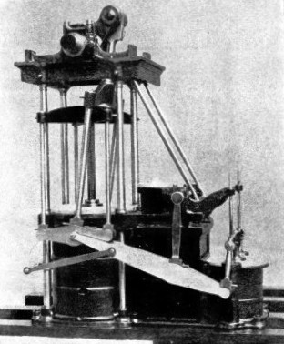 An interesting model of a quadruple piston-rod engine is preserved in the Science Museum at South Kensington. The model was originally used for propelling a small boat and has two cylinders 4½ in. diameter by 5⅓ in. stroke. The cranks are arranged at right angles and the valve chests contain long D-slide valves, worked by weight-shafts and gabs, from loose eccentrics on the crankshaft. The jet condenser formed part of the engine bed plate and was provided with an air pump of 3 in. bore and stroke, worked by a crank on the paddle shaft. A boiler feed pump was driven from the shaft by an eccentric.
DIRECT-ACTING PADDLE ENGINES of this type were fitted to several early tug boats. The piston rod is attached to a four-armed cross-head from which descend four rods, two on either side, to a pair of cross-pieces. To these cross-pieces are attached the ends of a long forked connecting rod. The side levers are controlled by a “Gorgon” parallel motion and drive the air- and bilge-pumps. The condenser is arranged between the cylinder and the pumps.
Napier’s steeple engine was further improved at a later date by the use of only two piston rods instead of four. The cylinder was placed vertically beneath the crankshaft, and the two piston rods passed through the top cover, extending upwards on either side of the shaft. Above the crankshaft, the piston rods were joined together by a crosshead working in cylindrical guides. The connecting rod worked downwards from the crosshead on to the crankshaft. From the crosshead also were worked the air- feed- and bilge-pumps, driven by links and beams. Steam distribution was by slide valves of the locomotive type operated by link motion. An interesting feature of this valve gear was the provision of teeth on the link, which could be moved by a hand-wheel and pinion for reversing or varying the cut-off of the steam supply to the cylinder.
S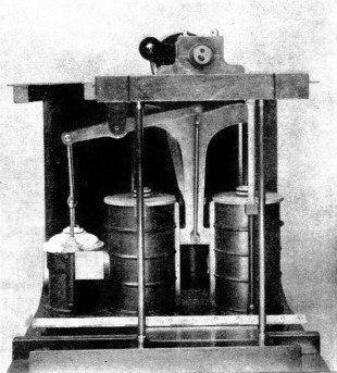 everal engines of this type were built for the East India Company in 1850. The engines were of 30 h.p., with single cylinders 2 ft. 8 in. diameter by 3 ft. 6 in. stroke and were for use in shallow-draught river steamers.
TWIN-CYLINDER “SIAMESE” ENGINES were fitted to H.M.S. Retribution, a paddle frigate of 1844. The arrangement permitted the use of long cylinders in a space limited in height. The cylinders were 6 feet diameter by 8 feet stroke. The model shows the T-shaped crosshead, from the lower end of which is taken a long connecting rod to the paddle shaft. H.M.S. Retribution was of 1,641 tons, with a length of 220 feet and an armament of ten guns.
Methods of providing a long connecting rod for the paddle engine continued to be devised. The use of a “return piston rod” proved an interesting addition to the various devices employed, and in this type of engine a single piston rod was terminated in a four-armed crosshead. The cylinder was placed in the usual position below the crankshaft. From the crosshead four rods passed downwards to a pair of short cross-pieces, guided in the up and down directions by side levers and parallel motion. A forked connecting rod extended upwards from the cross pieces to the crankshaft. Air and feed pumps were worked from the side levers and the condenser was situated in the engine framing between the air pump and the cylinder.
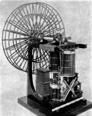
In 1843 a type of paddle engine was introduced with inverted cylinders and connecting rods returning upwards to the crankshaft. A set of these engines, by G. Forrester and Co., was installed in the paddle steamer Helen McGregor, built by John Laird at Birkenhead. These engines comprised two inverted cylinders, 3 ft. 6 in. diameter by 4 ft. 6 in. stroke, carried on four wrought-iron columns. The columns served also to connect the foundation plate with the entablature and crankshaft pedestal. The cylinders were arranged athwart-ship with piston rods projecting downwards and connected at their lower ends by a crosshead. The crosshead was guided by parallel motion and from it worked a connecting rod, swinging between the two cylinders. All the pumps were worked from the parallel motion of the crosshead, and the air pump was connected by a passage in the foundation plate to the condenser, which was placed beneath the valve chest. The steam pressure was low - only 3¾ lb. per sq. In - supplied by tubular boilers; and the paddle wheels, 23 ft. 6 in. diameter, revolved at 23½ revolutions a minute.
 The dimensions of the Helen McGregor, built for the Hull and Hamburg trade, are interesting, as she was at the time one of the largest vessels of her class. The length was 180 feet, breadth 26 feet, depth 15 feet with a register of 573 tons.
THE HELEN McGREGOR, a paddle steamer of 573 tons, was built at Birkenhead in 1843 and fitted with engines of the type illustrated here. The cylinders, 3 ft. 6 in. diameter by 4 ft. 6 in. stroke, were carried in an inverted position on four wrought-iron columns. The two piston rods were attached to a common crosshead, guided by parallel motion, and from this a connecting rod drove upwards on to the crankshaft. The Helen McGregor was 180 feet long and the inverted-cylinder engines saved a length of 25 feet of machinery space, compared with a side-lever unit of similar power.
The foregoing variations in paddle engine design do not exhaust the number of ingenious arrangements resorted to by the earliest marine engineers. The double-cylinder, or “Siamese”, engines of 1844 are of special interest, and were patented (as were the “Steeple” engines of 1839) by Maudslay and Field. Engines of the “Siamese” type were installed in the paddle frigate Retribution designed by Sir W. Symonds and launched at Chatham. H.M.S. Retribution was of 1,641 tons, 220 feet in length, with a breadth of 40 ft 6 in. She was 26 ft. 4 in. deep, and carried ten guns.
There were two engines, each with two cylinders, 6 feet diameter by 8 feet stroke, placed in a fore-and-aft direction under the paddle shaft. The two piston rods were attached to either arm of a double T-shaped crosshead, the tail of which worked in guides between the cylinders. In the tail portion of the crosshead was attached the connecting rod working upward on to the crankshaft. From the lower end of the main crosshead were also worked, through connecting rods and beams, the air and feed pumps.
In a later chapter will be described one of the most fascinating of all marine engine types, the oscillating engine.
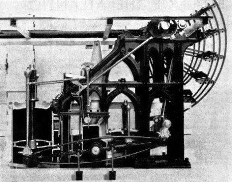
ROBERT NAPIER’S CLYDE-BUILT STEAMERS before 1845 were generally powered by side-lever engines of the type illustrated by this fine sectional model in the Science Museum at South Kensington. The ornamental cast-iron frames were a feature of these engines, and the set represented by this model had two cylinders, 5 feet diameter by 6 feet stroke, driving 24-ft. paddles at sixteen revolutions a minute. The piston rod was guided by a modified form of the parallel motion invented by James Watt.
You can read more on “Marine Engines and Their Story”, “Oscillating Paddle Engines” and
“Propelling the Modern Ship” on this website.


 The pivoted beam was arranged to keep the engine’s centre of gravity as low as possible and to save head room. It was the custom in those early days of steam to ornament the large stationary engines on land, and the extension of the practice to marine machinery is demonstrated in the model by Gothic framing supporting the paddle shaft.
 The engines of the Ruby, built by Seaward and Co., consisted of two cylinders 3 ft. 4 in. diameter by 3 ft. 6 in. stroke. Steam was supplied by flue boilers at a pressure of 3½ lb. The engines developed 100 h.p. and drove a pair of paddle-

 An interesting model of a quadruple piston-
 everal engines of this type were built for the East India Company in 1850. The engines were of 30 h.p., with single cylinders 2 ft. 8 in. diameter by 3 ft. 6 in. stroke and were for use in shallow-
 The dimensions of the Helen McGregor, built for the Hull and Hamburg trade, are interesting, as she was at the time one of the largest vessels of her class. The length was 180 feet, breadth 26 feet, depth 15 feet with a register of 573 tons.