

© Shipping Wonders of the World 2012-

Oscillating Paddle Engines
An account of the remarkable oscillating paddle engines of the last century and of the introduction of the surface condenser, an important development in marine engineering
MARINE ENGINES AND THEIR STORY -
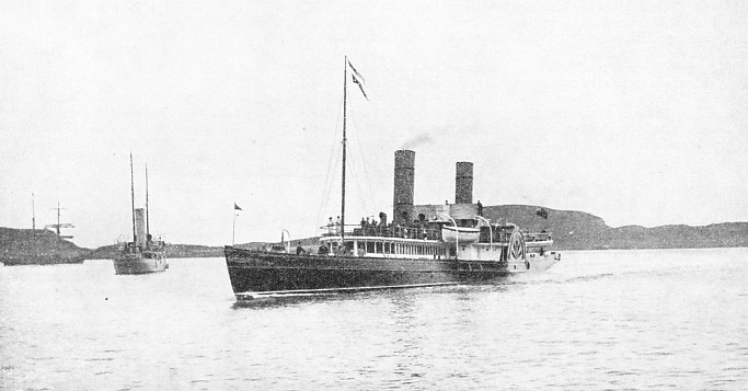
BUILT IN 1864, the Iona, a famous Clyde paddle steamer, saw over seventy years’ service in Scottish waters. The Iona was built and engined by J. and G. Thompson, of Clydebank. She had a gross tonnage of 396 and a speed of 17 knots.
ONE of the most interesting of all marine engine types is, perhaps, that known as the oscillating engine, in which the cylinders swing on trunnions -
In 1827 Joseph Maudslay adopted the oscillating cylinder arrangement independently and patented a marine engine of this type, with an improved valve gear. An interesting model of Maudslay’s oscillating cylinder marine engine is preserved in the Science Museum at South Kensington.
The engine has two cylinders, placed below the crankshaft. The condenser is between the cylinders and contains the air pump, driven from a crank on the shaft above it. The shaft is carried on A-
Piston rods pass through glands in the top cylinder covers, and the D-
Substantial improvements were made in the marine oscillating engine from time to time, notably by the famous engineer John Penn of Greenwich. Valve chests were placed on the cylinder sides between the trunnions, thus producing a more compact engine. To reduce weight, cast iron frames gave place to wrought iron columns and improvements were also effected in boiler design by the adoption of water tubes.
An oscillating engine with three cylinders was patented by Scott Russell in 1853; in this one cylinder was placed vertically and the others at 60 degrees to it. This arrangement gave an even turning movement to the paddle wheels, and was successfully employed in the Egyptian Government yacht Cleopatra in 1858. These engines were of 882-
On their introduction, oscillating engines were not favourably received by marine engineers, as their movement in the confined space of a ship’s engine-
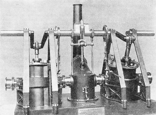
MAUDSLAY’S OSCILLATING ENGINE, patented in 1827, consisted of two cylinders swinging on trunnions. Steam was supplied to the cylinders through the outer trunnions, which were connected to the valve chests by passages cast in the cylinder walls. The inner trunnions were connected direct to the central condenser, which was fitted with an air pump worked by an intermediate crank. The slide valves of either cylinder were worked by an eccentric fitted with a catch for hand operation when reversing. Maudslay fitted engines of this type to the steamer Endeavour that plied on the Thames between London and Richmond from 1829 to 1843.
The Pacific, an iron ship of 1,469 tons, was built and equipped with oscillating engines by J. S. Russell & Co. in 1853. These engines were of 1,684-
Feathering floats were introduced in 1815, as explained in the earlier chapter “Marine Engines and Their Story”, by Baird in his paddle steamer Elizabeth, and the later development of the mechanism operating the floats is worthy of note. To provide a feathering action in large paddle wheels, floats were pivoted at either end, and to the back of each float was secured a projecting arm of iron.
The ends of the arms were connected by long rods to a ring or disk, free to revolve, but set with its axis eccentric to the axis of the paddle shaft. One of these rods, known as a master-
The boilers of the Pacific are of special interest, as they were among the first “box” or rectangular boilers to be fitted with tubes instead of flues. The use of tubes for box boilers was suggested in 1845 by the Earl of Dundonald, and rectangular multitubular boilers were extensively employed after 1850.
Paddles and Screw
The steam pressure of the Pacific’s four boilers was 18 lb and they contained 1,760 tubes, each 6 feet long and 3-
Among the largest oscillating paddle engines ever built were those of the Great Eastern, of 1858. This vessel, with a gross tonnage of 27,384, had, in addition to her paddles, a screw driven by separate engines.
The cylinders, four in number, were 6 ft 2-
The Mersey, an iron-
In 1860 a fleet of four iron vessels was built for the service between Holyhead and Kingstown (Dun Laoghaire). One of these ships was the Leinster, and models of her hull and machinery may be seen in the Science Museum at South Kensington. The engines were of the oscillating type, representing a high state of marine engine development. They indicated 4,751 horse power.
The two cylinders, placed immediately below the paddle shaft, were 8 ft 2-
An ingenious device was employed to ensure that the valve motion worked independently of the cylinder’s oscillation. The arrangement comprised a sliding rod driven by the eccentric; on the lower end of this rod was a curved slot accommodating two slide-
The steam generating plant in the Leinster comprised eight multitubular boilers, supplying steam at 20 lb pressure. The boilers were arranged in pairs with the backs towards the ship’s sides, leaving a central alleyway for stoking. Four boilers were placed forward and four abaft the engines.
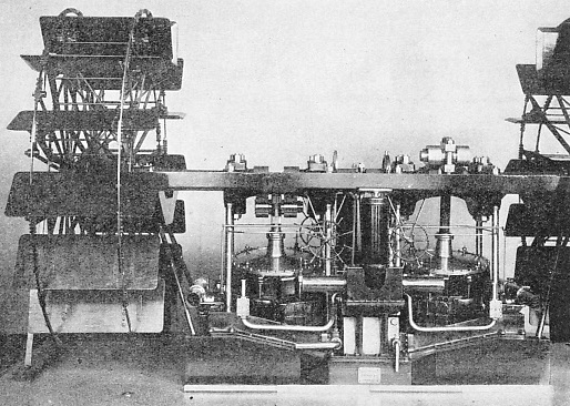
THE ENGINES OF THE LEINSTER, an iron paddle steamer of 2,000 tons, built in 1860, are represented by this fine model in the Science Museum at South Kensington. The Leinster's engines had two oscillating cylinders, 8 ft 2-
The boilers were each 9 ft 3-
Feathering paddle wheels were employed and these were 32 feet in diameter, each with 14 floats, 12 feet long by 5 feet wide. On her trial trips the Leinster attained a speed of 17¾ knots, with the engines making 25½ revolutions a minute on a steam pressure of 20 lb. The vessel was 343 feet long and 35 feet beam, with a depth of 19 feet, a draught of 13 feet and a displacement of 2,000 tons.
The beam engine of an American river steamer, illustrated below, is of particular interest. The photograph is of a model, built to a scale one-
The engine has two A-
The valve gear is of a special type patented by Francis B. Stevens in the U.S.A. in 1841. In front of the cylinder are two cylindrical valve chambers, to the top and bottom of which are connected castings containing the valve seats. There are a steam and an exhaust valve at either end of the cylinder and the valve chests are connected by two hollow columns or valve chambers. The left-
River Paddle Steamers
The Stevens steam cut-
These remarkable beam-
Among the paddle engines of various types that have already been described, some used steam to create a vacuum by condensation, thus permitting the atmosphere to perform the working stroke of the piston. Others used steam at an exceptionally low pressure, necessitating the employment of large cylinders, with the attendant difficulties of finding room for the engines in the confined space of a ship’s hull. The boilers of those early days were often only strong enough to hold the weight of the water they contained. For this reason, special relief valves had to be fitted to let in the air. If they had not been fitted, the pressure of the atmosphere would have crushed in the plates, when the boiler cooled down, against the partial vacuum inside.
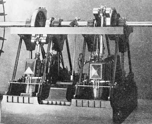
PADDLE ENGINES OF THE GREAT EASTERN. These engines were of the oscillating type, and comprised four cylinders, 6 ft 2-
Very low pressures, from about 3 to 5 lb, were not generally exceeded in Great Britain until 1835, but in America the Mississippi steamers used pressures as high as 140 lb per sq in. River steamers had the advantage of unlimited fresh water for supplying the boilers. Seagoing vessels, however, used sea water for the boilers, and consequently pressures rarely exceeded 20 to 25 lb until after 1860, when the surface condenser began to be adopted for ships’ engines.
The use of sea water in boilers resulted, of course, in the deposit of a layer of salt on those surfaces from which heat should have been obtained to generate steam. This made the use of high pressures impossible, especially as the brine had to be “blown out” of the boiler periodically.
Blow-
Hall’s Surface Condenser
In the surface condenser the steam is condensed without mixing with the sea water used for cooling. This condenser comprises a tank containing a large number of tubes through which sea water is pumped. Exhaust steam enters the tank and condenses against the cool tubes, so that the water thus formed is reasonably pure and can be used in the boilers continuously. Both James Watt and David Napier had invented surface condensers, but the credit for the practical development of the device is due to Samuel Hall, who patented his condenser in 1831.
In Hall’s condenser the exhaust steam was passed through a number of copper tubes in a tank, through which cooling water was pumped. In modern surface condensers the cooling or circulating water is pumped through the tubes, against which the exhaust steam condenses externally.
Hall’s condensers were installed in the paddle steamer Wilberforce in 1837, and gave satisfactory service on the London to Hull service until 1841, when the outside of the tubes was found to be coated with Thames mud. Her surface condensers were therefore replaced by those of the jet type, and for many years there existed a prejudice against Hall’s invention.
In 1859, however, a surface condenser was installed in the P. & O. steamer Mooltan, and this was found to be quite successful in operation. Later the surface condenser was generally adopted, and its use had a marked influence on the development of the marine engine.
The surface condenser was devised primarily to keep marine boilers clean by using fresh water, and to save the heat wasted in “blowing out” the brine when sea water was used for the generation of steam.
Apart from attaining increased boiler efficiency, however, the surface condenser paved the way to higher steam pressures for marine work. The use of higher steam pressures became increasingly important with the search for greater thermal efficiency in the operation of the steam engine.
When using steam in one cylinder only, there are considerable heat losses due to the alternate heating and (partial) cooling of the cylinder walls. This difficulty is to a certain extent overcome by using steam at a high pressure, first in one cylinder and then at decreased pressure in a second cylinder. This method of using the steam expansively is known as compounding. If a third cylinder be added we have “triple-
Compounding can be resorted to satisfactorily only when the initial steam pressure is high, and this need for multi-
On the Thames, experiments were carried out with small paddle steamers using high-
High pressures, with compound or triple expansion working were, however, gradually adopted and most present-
This diagonal arrangement of the marine engine for driving paddle wheels was originally patented by Marc Isambard Brunel, the famous engineer, in 1822. Among the finest engines of this type were those of the sister ships Princesse Henriette and Princesse Josephine, built and engined at Dumbarton in 1888, for the Ostend-
expansive use of the steam was derived from a lever attached to the main crosshead of each piston rod. The variation in the amount of steam supplied to the cylinders for each stroke, or “linking up” as it is termed, was controlled by Brown’s steam reversing gear.
With the increasing size of marine engines and the greater weight of the component parts, the provision of power-
Paddle Steamer Built in 1932
A cylindrical condenser was used and the shell was constructed of steel plate. Two vertical air pumps, 34-
The paddle wheels were of the feathering type, 24 feet diameter and 13 ft 6-
A fine working model of these engines can be seen in the Science Museum at South Kensington.
For general purposes, paddle steamers must be regarded as obsolete as far as ocean voyages are concerned, but they are still built for service in special conditions, especially where shallow draught is essential. Reference has already been made in this chapter to the river steamers of the U.S.A. and to the stern-
For tourist and excursion traffic round the coasts of Great Britain, the paddle steamer is much in demand. The General Steam Navigation Company, for example, owns a number of such steamers, including one that was completed as lately as 1932. This is the Royal Eagle, built for the passenger service between London and Margate, and equipped with three-
In a later chapter an account will be given of the gradual development of the paddle wheel’s successful rival -
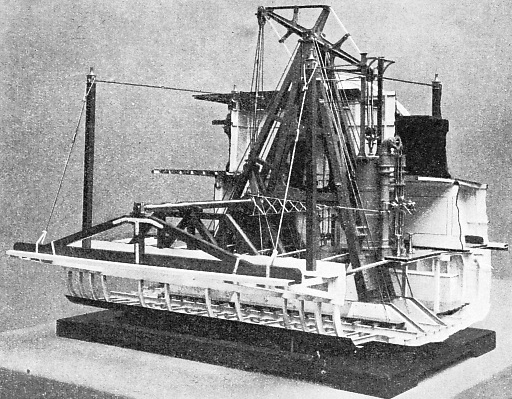
AMERICAN RIVER STEAMERS were equipped with beam engines, and the model illustrated shows the machinery of a type of paddle steamer built in 1884. The cylinder is 3 feet bore, with a stroke of 9 feet, and drives the paddle shaft by a beam supported on massive A frames The paddle wheels are 24 ft 10-
You can read more on “Coastal Pleasure Steamers”, “The Development of the Screw Propeller” and “The Mississippi”on this website.