

© Shipping Wonders of the World 2012-

Development of the Screw Propeller
Steamships had been propelled by paddle wheels from the earliest days until the middle of the last century, when experiments with screw propellers were successfully carried out and the screw-
MARINE ENGINES AND THEIR STORY -
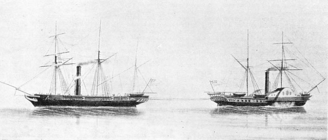
TUG-
WE have traced in earlier chapters the story of the marine engine as applied to paddle steamers. The screw propeller, however, has been universally adopted for all ships except those used for pleasure excursions and for navigation on shallow rivers and lakes. It was not until the paddle steamer had reached a high standard of efficiency that the screw propeller was generally adopted by the marine engineer. But for many years propulsion by screws had been suggested from time to time by various inventors. As early as 1729 an inventor named Du Quet suggested a screw for propelling ships, and similar proposals were made by Daniel Bernoulli in 1752 and by Bramah in 1785.
In 1794 a triple-
A similar device was invented by Edward Shorter in 1800. This consisted of a two-
Edward Shorter also suggested that his propeller might be driven by a steam-
In 1836 Francis Smith, a farmer at Hendon (Middlesex), patented a single-
This launch was tried on the Paddington Canal, where, in 1837, a fortunate accident led to further improvements in ship propulsion. During one of the launch’s trips on the canal, half of the wooden propeller was broken off, and to the surprise of the crew the speed of the craft was immediately increased. A metal screw, consisting of one complete turn instead of two, was then fitted to the F. P. Smith, and she subsequently made some voyages in the Thames estuary from London to Folkestone at a speed of about five and a half knots.
After these experiments Smith amended his patent specification in 1839 and his screw was described as consisting of a single turn or alternatively a double thread with two half-
It was also at Hendon -
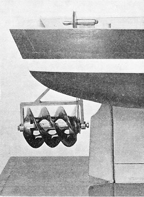
A TRIPLE-
A company was formed to exploit Smith’s amended patents of 1839, and in the same year the Archimedes (237 tons) was launched. She was equipped in the first instance with a single-
The Archimedes attained a speed of nine knots and, in addition to the circumnavigation of the British Isles, she made a voyage to Oporto, in Portugal. These successes proved the suitability of the screw propeller for marine purposes, and Francis Smith was knighted in 1871 for his services to shipping.
The famous engineer, John Ericsson, of Sweden, after his retirement from the Swedish army, settled in England and worked independently of Smith. In 1836 he patented a screw propeller consisting of two drums on a shaft. Either drum had a series of helical blades round the periphery, and the blades on one drum were inclined in the direction opposite to those on the other drum. An interesting feature of Ericsson’s propeller was the arrangement of the two drums. These were mounted on a common axis, but they revolved in opposite directions. The after drum revolved at a faster speed because it acted in water that had already been set in motion by the forward drum.
The reversed direction of the after drum was intended to counteract losses caused by the rotary motion of the water behind the leading drum. The arrangement of duplex screws was not adhered to in marine practice, because experience indicated that the complication involved did not improve performance. Ericsson himself often made use of a single screw. A survival of twin screws revolving in opposite directions on one shaft is found in the modern torpedo. The arrangement is there used to counteract the “torque” or force that would endeavour to turn the torpedo over against the direction of a single propeller’s rotation.
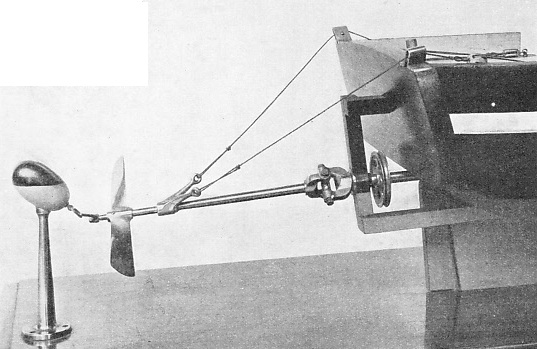
PATENTED IN 1800, Edward Shorter’s screw propeller was described as a “ perpetual sculling machine”. The screw was submerged in the ship’s wake and was prevented from sinking by the buoy. Manually operated, the screw was given a trial in the transport Doncaster, in 1802. The best speed was under two miles an hour.
Francis Smith, as we have noted, used models for his early experiments and Ericsson adopted similar measures. He experimented with a model ship in a circular tank, from the centre of which projected a tubular arm. The model was fitted with a propeller driven by a small steam engine. Steam was supplied to the engine through the rotating tubular arm.
The first practical test of Ericsson’s propeller was carried out on the Thames in 1837. A 45 ft boat, the Francis B. Oyden, was fitted for screw propulsion. She towed the Admiralty barge, with some of the Lords of the Admiralty on board, from Somerset House to Blackwall and back at an average speed of ten knots.
After other experiments had been carried out, a United States naval officer, Captain R. F. Stockton, arranged for the construction of a vessel 70 feet long by 10 feet beam, with engines driving direct on to the propeller shaft. This ship, the Robert F. Stockton, was built at Birkenhead by Laird Bros, in 1838, and attained a speed of thirteen knots with the tide. She crossed the Atlantic under canvas early in 1839 and saw many years service as a tug in New York harbour under the name New Jersey. Ericsson left for the United States later in 1839. There his invention was used in a number of American river steamers and in the U.S. warship Princeton, built in 1842.
The superiority of the screw propeller over the paddle wheel for the propulsion of ocean-
This test, however, cannot be regarded as conclusive in favour of the screw. The Rattler’s engines developed 300 indicated horse-
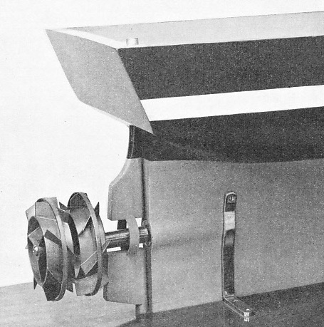
TWO PROPELLERS IN ONE, as now used in an improved form for the modern torpedo. This form of screw was the invention of Captain John Ericsson, the famous Swedish engineer, in 1836. The forward drum, fitted with helical blades, revolved in one direction and the after drum was turned in the opposite direction at a faster speed.
The engines of H.M.S. Rattler were of Maudslay’s “Siamese” type and drove the shaft through spur gearing which increased the propeller speed to 113 revolutions a minute, or four times the speed of the crank. The propeller is preserved in the Science Museum at South Kensington. With a diameter of 10 ft 1¼-
The development of the screw propeller was due to many factors apart from efficiency. A screw propeller cost less than a pair of paddle wheels. It was also more convenient to fit in a ship’s hull, as it required no sponsons or paddle boxes.
For the propulsion of warships, the obvious advantages of the screw were fully appreciated, though the Admiralty at first thought this method of propulsion would interfere with steering. The outstanding advantage of the propeller over paddle wheels for naval use was, however, its comparative immunity from the effects of gunfire. Propellers were generally completely submerged and the motive power was housed below the water line.
Another reason for the preference of the screw propeller was that it could be used more readily than paddle wheels as an auxiliary means of propulsion for sailing vessels, or for driving ships during calms. Paddle wheels in a sailing ship under canvas were scarcely an asset when stationary, for the paddles acted as highly efficient anchors and retarded progress enormously. Various expedients were tried to enable a paddle ship to discard her wheels in a fair wind. Floats were constructed to move inwards towards the paddle shaft. Sometimes the wheels were so made that they could be dismantled at sea and stowed on deck when not required.
The drag of an idle screw-
Other devices included the use of propellers with movable blades which could be adjusted from within the vessel. A two-
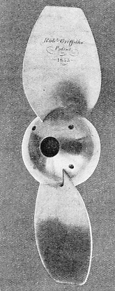
After the valuable work of the early pioneers in propeller design, a type of screw was evolved that was in general use until about 1860. This was known as the common screw, and had wide tipped blades and a small cylindrical boss. The common screw, however, had two main disadvantages. The portions of the blades nearest the boss served no useful purpose and were in fact a source of weakness, for the boss was made as small as possible. The wide, fan-
In addition to Robert Griffiths there were other inventors, both before and after his time, who devoted their energies to the improvement of the screw propeller. The problems associated with screw propulsion are complex. Size, weight, revolutions a minute, the number of blades and their shape, all have to be considered in designing an efficient propeller. The correlation of all the qualities that combine to make the ideal propeller is a task involving great technical skill, but some of the difficulties met with in this branch of marine engineering may be stated without discussing the matter in all its purely scientific aspects.
A ship’s screw acts on water that is not at rest. A ship as she moves forward carries some water with her, and the shape of the hull aft materially affects the screw’s performance because of its influence on the way the water approaches the screw. If we regard the approaching water in the form of a cylindrical column whose velocity is increased by the action of the screw, such a column should be decreasing in diameter to yield the maximum efficiency.
Problem of Vibration
It is obvious in these circumstances that there should be no outward movement of the column of water, as this would cause its diameter to increase.
Many inventors have designed propellers that were intended to overcome this difficulty. In 1843 the Earl of Dundonald patented a propeller with the blades inclined aft to prevent any outward flow of water. Other inventors provided concentric ridges on the blades to achieve the same object, and some screws were sickle-
Another problem that propeller designers tried to solve related to the backward motion imparted to the water by the leading or fore-
Vibration is an ever-
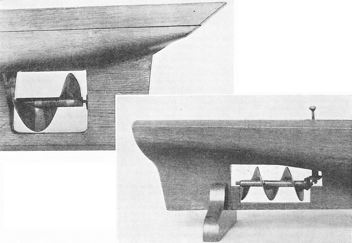
THE ORIGINAL FORM of the screw propeller patented by Sir Francis Smith is seen on the right. In 1836, the launch F. P. Smith, fitted with this screw, was given a trial on the Paddington Canal, London. Half of the screw broke off, and this gave the vessel a considerably faster speed. The inventor then devised the screw with a single turn, as shown above. This is, in effect, a two-
Since the time of Smith and Ericsson great improvements have been effected in the design and construction of marine screw-
The fact that the propeller shaft was even lower in the ship than the crankshaft of a paddle-
Many and ingenious were the devices subsequently employed to fit engines of the requisite power in the confined space of a ship’s hull. Designs for marine engines followed one another ceaselessly as improvements were dictated by experience and careful experiment. Finally the vertical reciprocating engine was evolved, with inverted cylinders mounted on framework fore and aft in line with the propeller shaft. The gradual process of determining the best position for the reciprocating steam engine in a ship led to the ideal arrangement for the multi-
The early screw engines, in common with their contemporary paddle-
 It has been shown in the earlier chapter “Marine Engines and Their Story” how the first paddle engines were evolved from the massive stationary engines used on land. Even the ornamental iron framework, despite its weight, was faithfully copied for marine use.
MODERN PROPELLER DESIGN is based on the screw shown here. This screw was patented by Robert Griffiths in 1855. To the central boss, about one-
The first screw engines similarly exhibited the main features of the engine then in use for driving paddle wheels. The marine propeller, however, requires a higher rate of revolution than the paddle wheel. Means had therefore to be adopted to “speed up” engines to meet the new conditions imposed by screw propulsion. To obtain a faster propeller-
An exception to the use of geared engines was the method employed in the steamer Robert F. Stockton of 1838. referred to above. This vessel was driven by direct-
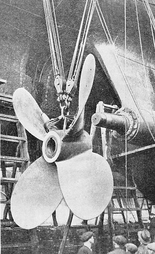
FIFTEEN FEET IN DIAMETER, the propeller shown right is being fitted to one of the tail-
You can read more on
“Propelling the Modern Ship” and
“The Queen Mary's Engines” on this website.