

© Shipping Wonders of the World 2012-

Modern Marine Boiler Types
Considerable improvement in the power and efficiency of marine boilers followed upon the adoption of the Scotch boiler about 1870 and has continued with the subsequent development of the water tube boilers
MARINE ENGINES AND THEIR STORY -
SCOTCH BOILERS were introduced in 1862, and until water tube boilers were perfected Scotch boilers were generally used in ships. Even to-
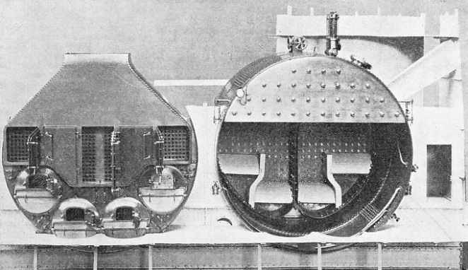
FROM 1870 until the introduction of the water tube boiler the “Scotch” type predominated in the steamers and warships of the world. In merchant vessels the Scotch boiler is still the type most frequently employed and is able to work at pressures up to 300 lb.
When first generally introduced the working pressure of the Scotch boiler was about 60 lb. This was steadily advanced until it had reached 135 lb. by 1889-
The shell of the boiler was made in the form of two rings joined together by trebly-
On either side of the boiler, adjacent pairs of furnace flues were led into a common combustion chamber. These chambers were approximately quadrant-
The flat sides of the combustion chambers were stayed together by screwed rods, and their roofs were strengthened by girder stays. Each chamber was provided with 245 return tubes, 2½ in. in external diameter, leading to a smoke-
Supported in cradles, the boilers were secured to the inner plating of the hull. The boilers, three on either side, were placed with their backs against the plating of a central tunnel, 10 ft. 6 in. wide, which divided the engine and boiler rooms at the middle of the ship and was used for the transfer of ammunition from one end of the vessel to the other.
There were thus two separate stokeholds and either could be rendered airtight by screens and air-
 The boilers in H.M.S. Trafalgar were each 16 ft. 1 in. in diameter and 10 ft. 3 in. long. In working order, with fittings and including its proportion of uptake and funnel, each boiler weighed 84 tons. The heating surface was 3,050 sq. feet and the steam output under natural draught was equivalent to 1,400 indicated horse-
Scotch boilers have been improved considerably in detail since their introduction, but their general working principles are still incorporated in modern designs for this type of marine steam generator.
BOILERS OF FRENCH ORIGIN were the first of the water tube type to be extensively used. The Belleville boiler, illustrated here, was introduced about 1850, but not until 1893 was an improved type used in a British warship. In 1895 H.M. cruisers Powerful and Terrible were equipped with Belleville boilers.
The water tube boiler has now superseded the Scotch boiler for Naval use and is being used more extensively in the Merchant Service, especially for large passenger liners. Its story is even older than that of some other types of boilers. In 1766 William Blakey patented a boiler that was fitted with inclined water tubes. A water tube boiler was used by James Rumsey in his jet-
Colonel John Stevens's twin-
The first water tube boiler to be used extensively in marine practice was the Belleville, named after its inventor, a distinguished French engineer. First introduced about 1850, the Belleville boiler was modified in later years, and by 1880 it comprised a series of slightly inclined, large diameter tubes arranged close together in separate groups.
The improved Belleville boiler was successfully used in French warships and passenger steamers. In the Royal Navy, Belleville boilers were fitted in the torpedo-
F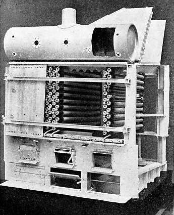 our boilers were built together into one unit and each boiler contained eight elements. The mild steel tubes had an external diameter of 4½ in. and a length of 7 feet. They were screwed into malleable cast iron “bends” or junction boxes placed one on top of another. Steam generated in the element tubes carried with it much water to the steam drum. Such water was, however, separated by a system of baffles and returned by vertical pipes to mud drums at either end of the feed collector. Lime-
Eighteen Niclausse boilers, as shown here, were fitted in H.M.S. New Zealand. Each boiler had a heating surface of 1,992 square feet and worked at a pressure of 220 lb. per square inch.
In the front of the boiler a square tube was fitted, and this was supplied with compressed air discharged through nozzles into the furnace to assist in the combustion of the fuel. Above the water tubes were placed deflector plates to help in the circulation of the furnace gases.
Each boiler had a heating surface of 1,500 sq. feet and worked at a pressure of 250 lb., giving a steam supply equivalent to over 500 indicated horse-
Another interesting boiler of French origin was the Niclausse. In this type of boiler inclined tubes, closed at one end, had within them circulating tubes that led into separate water compartments or headers. Eighteen of these boilers were fitted in H.M.S. New Zealand in 1904. Each boiler contained sixteen elements, each comprising a malleable cast iron header with twenty steel tubes. The headers were divided into two compartments, but all were connected at the top to a common steam drum. The back compartments of the headers communicated with the larger or outer inclined tubes. The smaller tubes inside were connected to the front header compartments. These double tubes ensured circulation of the water in the boiler which had a heating surface of 1,992 sq. feet and worked at a pressure of 220 lb. A type of inclined tube generator that was originally introduced into the United States Navy in 1889 was the Babcock and Wilcox boiler. This has been extensively used in the Royal Navy also since 1898. The inclined steel tubes of this boiler are straight and are expanded into wrought steel headers arranged vertically. The tubes slope downwards towards the front of the boiler, and the upper ends of the front headers are connected with an overhead steam drum. This drum is also connected with the tops of the back headers by horizontal tubes. The lower ends of the front headers are connected to a steel sediment box of square section.
First Naval Water Tube Boiler
The first water tube boiler to be used in the Royal Navy was patented by Sir John I. Thornycroft in 1885. This type of boiler was fitted in H.M.S. Speedy, a torpedo-
In the “Speedy” Thornycroft boiler a central steam drum, arranged at the apex of an inverted V, was joined by a large number of small-
A special feature of the Thornycroft boiler is the provision of large-
A modified form of the above type was the Thornycroft-
This type of boiler had an upper steam drum connected to a central lower water drum by eight curved downcomers, and to each of two outer water drums by straight downcomers outside the boiler casing. The steam and water drums were also connected by water tubes forming the sides and crowns of the furnaces. There were 1,764 water tubes, with a total heating surface, including internal downcomers, of 4,040 sq. feet. The furnaces were lined with firebrick and the whole boiler was enclosed in a thin sheet-

A MODIFIED FORM of the Thornycroft boiler patented in 1885 was the Thornycroft-
In 1893 a type of boiler used in the Royal Navy for torpedo boat destroyers was patented by J. W. Reed. Boilers of this design were installed in the “River” class of destroyers in 1904. The Reed boiler had a steam drum connected at either end by downcomers with two horizontal water drums. The steam and water drums were also connected by a large number of curved water tubes within a double steel casing lined with asbestos.
Another type of boiler extensively used in the Royal Navy was that originally patented by Sir Alfred F. Yarrow in 1889. For use in torpedo-
In 1903 a number of large-
An interesting contrast is the type of Yarrow boiler built about 1924 and arranged for oil-
The water drum on the superheater side of the boiler is smaller than that on the other side and has fewer water tubes. This construction is adopted to balance the resistance of both sides of the boiler to the flow of furnace gases.
The water tubes connecting steam and water drums are arranged in unequal “nests” and the tubes of the two rows of each nest nearest the fire are thicker and larger than the remainder of the tubes.
Another important fitting in this boiler is a funnel uptake damper used for deflecting hot gases from the superheater when the engines are stopped or slowed down. The output of this type of boiler is equivalent to 12,000 indicated horse-
The Yarrow boiler is the form most extensively used for marine purposes and is fitted in all types of British warships. In general principles the design of this generator conforms to the original ideas of Sir Alfred F. Yarrow, but, with the introduction of oil-
A modern Yarrow boiler has 12,444 sq. feet of heating surface, 6,577 sq. feet of superheating surface and another 14,629 sq. feet for heating the air that is forced in for the combustion of the fuel oil. There are seven oil burners, and the working pressure is 425 lb., with steam superheated to 725° F.
Another type of boiler which has given satisfactory results is that introduced by Mr. J. J. Johnson about 1929. The Johnson boiler consists of two large drums placed vertically one above the other and connected together by curved tubes. In addition to these tubes there is a water tube wall between the drums. This divides the combustion space into two compartments. Either compartment is provided with three oil burners of the spraying type. Interspaced between the generator tubes, superheater tubes are arranged at the top of the boiler.
The furnace gases, having given up most of their heat to the generator and superheater tubes, pass through a large tubular air heater on their way to the funnel uptakes. The generator tubes of the Johnson boiler give 6,841 sq. feet of heating surface, with an additional 3,840 sq. feet in the superheater. The air heater has an area of 23,943 sq. feet. The boiler pressure is usually about 425 lb., with a superheat to 725° F.
B oilers of these types, however, are not restricted to a working pressure of 425 lb. Steam may be generated in them to a pressure of 575 lb., but even this figure does not represent finality. A type of boiler known as the Benson generates steam at 3,200 lb. per sq. in., supplied through a reducing valve to high-
LARGE-
The marine steam boiler has certainly seen many and drastic changes since its introduction to man’s service.
Perhaps the most spectacular change of all is the change from coal to oil firing. Gone are the days of the “blacksquad” toiling in stokehold infernos on board liners and warships. The quietly swirling sheets of oil-
You can read more on “Marine Engines and Their Story”, “Propelling the Modern Ship” and
“The Queen Mary’s Engines” on this website.
You can read more on the “The Yarrow Water Tube Boiler” in Wonders of World Engineering