Main features of the powerful and sensitive equipment that keeps the vessel in constant touch with other ships and with the shore

THE OPERATOR’S DESK is generally placed against a bulkhead, to which most of his instruments are fixed. His telephones are shown connected to terminals on the receiver fastened to this bulkhead. The two transmitting keys - main and emergency - are on the front of the desk, within easy reach of the operator’s right hand. This is a typical 1½-kilowatts valve installation of the type used in passenger-carrying vessels.
AT twenty minutes to six on a dark January morning in the North Atlantic, the look-out in the liner Republic saw a large vessel loom without warning from the surrounding fog, crash into the Republic on the port side and sheer away. With a suddenly flooded engine-room and an alarming list, the Republic floundered alone in the fog, with 710 souls on board - and the ship’s wireless set. In this setting the wireless installation was called upon to prove its value. There followed a demonstration which thrilled the world, and led to a universal demand that all large ships should be fitted with wireless apparatus.
The collision occurred on January 23, 1909, in latitude 40° 17’ N, longitude 70° W. The Republic, bound for Madeira, had left New York the day before, and during the night had run into a belt of fog. The vessel was proceeding slowly about twenty-six miles south of Nantucket Light, when she was rammed by the Italian steamer Florida.
Only six lives were lost when the vessels crashed together, but about 2,000 people were placed in imminent danger, for both ships were seriously damaged. The Florida, groping her way back and guided by fog signals, first took on board all the passengers. The doomed Republic sank, but not before her wireless had summoned the Baltic and other vessels. They reached the scene in time, transferred passengers and crews, and landed all those involved in the collision without further loss of life.

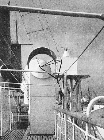
A wireless station is concealed in the dummy forward funnel of the Cunard White Star Liner Georgic. This ship is one of the largest motor vessels in the world, with a gross tonnage of 27,759. The lead-in cables from the main aerial can be seen in the upper right-hand corner of the picture. Above the funnel is the screened fixed-loop aerial for the direction-finder installed in the wireless cabin beneath. Port-holes provided in the funnel casing can be seen in the photograph.
The quality of the seamanship displayed on that occasion, the swift transfer in boats, the rescue of the Republic’s captain and crew when the vessel sank - these were all in the tradition of the sea. Further, a new tradition was inaugurated in the far-flung distress message, summoning vessels many miles out of sight by electromagnetic waves. On that day wireless, the new invention, vindicated itself as a large-scale life saver; apparatus similar to that of the Republic was soon fitted to other ships, and within a few years it was proved beyond question in all kinds of emergencies that science had provided mankind with another powerful aid to preserve the safety of life at sea.
The modern liner’s radio apparatus is, of course, entirely different from those early wireless installations. It is at once more powerful and more sensitive - literally millions of times more sensitive. The original ships’ wireless sets were designed primarily for safety: that they adequately served their purpose is recorded in many a story of rescued lives. In the modern liner the safety of life is still the primary purpose of the radio equipment. International laws compel all shipowners to fit certain classes of vessel with wireless transmitters and receivers, and to arrange that wireless watch shall be kept, in conformity with the various International Conventions for the Safety of Life at Sea. The means, however, have outstripped the end in view; and instead of being merely the instrument of making distress calls when tragedy has occurred, wireless is now devoted more to prevention than to cure.
To-day the liner bound across the Atlantic can communicate with radio stations in Canada and the USA before she has left Southampton Water, and she can easily exchange messages with sister ships plying anywhere on the route. She receives and sends out weather reports. She checks her chronometers by the time signals coming direct from observatory clocks. She has on board a wireless direction-finder that is absolutely independent of fog or any similar condition of bad visibility. Furthermore, not only is the captain kept in touch with his owners and with other vessels, but passengers are also continuously linked with friends at home and with business acquaintances by wireless. Most of the communications from ship to ship, or between ship and shore, are telegraphed in the Morse code, because this method is superior for fast long-distance working. But the larger vessels are equipped also with telephonic apparatus. The telephone in the ship then enables a passenger to take a call which has come through from a telephone subscriber ashore, and to answer as though from house to house. Since about ninety-five per cent of the world’s telephones are now interconnected by wireless and cables, there is scarcely a place in the world that cannot be reached by telephone from a liner in mid-ocean.
Wireless-Equipped Lifeboats
In some of the larger ships a passenger may speak from any of the ship’s telephones in the public rooms, or from his private cabin. Connexion is made between the wireless room and the selected telephone through the liner’s switchboard; thus the call between ship and shore can be made as conveniently as from one house to another in the same town.
There are also several other valuable applications of wireless technique that assist the seafarer. The Merchant Shipping Act now provides that all passenger-carrying vessels of 5,000 tons gross and upwards shall be fitted with wireless direction-finding apparatus. The invention of this equipment solved, once and for all, the navigator’s age-old problem of finding the ship’s position in fog or haze, which hides the sun, stars and horizon and thus prevents the use of the sextant.
Lifeboat sets are another part of the large liner’s wireless equipment. In the event of the boat becoming separated from others its miniature wireless set is able to serve the small community in much the same way as the main installation serves the ship herself.
Electric waves are used also for depth-sounding, the method depending upon a train of waves being directed down to the bed of the ocean. The waves axe reflected back to the ship and indicate the depth below by means of the time they take in transit. The apparatus can be worked from a single accumulator, and is hundreds of times faster in operation than the best wire-sounding machine. The downward-directed waves used in this method are more of the nature of sound than of wireless waves, but their detection and amplification on return from the ocean bed are an electrical process for which valve amplifiers are used.

ONE OF THE WIRELESS CABINS in a modern liner, showing on the left the 2-kilowatts medium and long-wave telegraph transmitter. On the desk is a marine receiver covering all wavelengths from 15 to 20,000 metres. Below the valve transmitter (left) is the generator plant, with motor starter and regulator on the front of the panels. The emergency spark transmitter is placed at the far end of the main transmitter which, in the picture, hides it from view. The aerial switch is placed above the receiver to the left, and to the right is seen a charging board, on the bulkhead, above the direction finder. Beside the table to the right is a pneumatic carrier, in which radiograms are placed for transmission to the ship’s bureau by means of the tube to the right of the farther desk.
Wireless apparatus in a ship includes the loudspeaker-and-amplifier equipment for distributing speech and music throughout the vessel. Apparatus of this kind is able to reproduce vocal music, the ship’s orchestra, gramophone records or speech; and it may be used in conjunction with a broadcast receiver for supplying programmes from shore stations to the various loudspeakers in the equipment.
These subsidiary applications of wireless are, however, of minor importance compared with the main transmitter and receiver, on which the ship depends for reliable communications. The passenger liner - with a thousand or more people on board sending farewells to the friends they have left, or greetings to those expecting them - must be capable of handling expeditiously the heavy flow of messages. The ordinary telegraph station is still, but that of the ship is moving, and this fact presents the operator with problems that do not arise in land-line and cable working, in her progress across the ocean the ship is always tending to lose touch with the wireless stations behind her, and to make new contacts with those she is approaching. Other liners pass and repass, their powerful transmitters creating interference on the wavelengths they use and necessitating the selection of different wavelengths on which communication can be maintained. Vessels large and small, of all nationalities, and with various types of apparatus, must work harmoniously to get their messages through. News bulletins must be received, bearings must be taken with the direction finder, and a watch must be kept for distress messages and navigational warnings.
The ship’s wireless receiver and transmitter must therefore be of special type, widely different from the corresponding apparatus used ashore. A typical valve receiver, for example, will be able to cover all the wavelengths from 15 to 20,000 metres. Its tuning must necessarily be far more intricate than that of the ordinary broadcast receiver, which cannot be tuned below 200 nor above 2,000 metres.

TELEPHONING TO THE SHORE FROM MID-OCEAN. Passengers in large liners can speak from their own cabins to friends on shore as easily as from house to house. Special equipment is necessary to provide such remarkable long-range telephone service, and only the larger liners are equipped for this purpose.
In addition to covering an extraordinarily wide band of wavelengths, the liner’s wireless receiver must be capable of picking up not only telephony (speech and music) as commonly heard ashore, but also the other forms of marine wireless communication in general use - continuous wave signals, spark signals and interrupted continuous waves. To minimize interference, which is generally at a maximum on wavelengths between 300 metres and 1,200 metres, a rejector circuit is often incorporated.
The valves are supplied with high-tension and low-tension current from accumulators, which are kept charged by the vessel’s electricity supply through a suitable charging- and switch-board. For use in emergency a plug-in type of crystal detector is provided. If necessary a high-frequency amplifying unit can be added to the standard receiver, but, for considerations of space, a general principle is to keep the apparatus as simple as possible. Simplicity, moreover, tends towards reliability - a vital necessity in ships’ wireless. Other exacting requirements are that the receiver should be unusually robust to withstand the heavy vibration and severe physical conditions imposed upon all parts of the structure of a ship; and that it should either remain unaffected by electrical or magnetic interference from other electrical equipment used on board, or should be capable of functioning despite such interference. It is generally screened thoroughly, and the various receiver units are enclosed in eases of sea-air-resisting aluminium alloy. This type of receiving unit has a weight of forty-six pounds, is thirteen and a half inches high, twenty-two inches wide, and ten and a half inches deep. The high-frequency amplifying unit used in conjunction with it is of the same size, but weighs fifty-two pounds.
A SHORT-WAVE TELEPHONE TRANSMITTING AERIAL in a Canadian Pacific liner. The aerial, which is of the “uniform” type, was specially designed for this class of work and leads into a transformer-coupling box. This is connected to the transmitter in the wireless cabin by means of concentric copper feeder tubes.
Most of the space in the wireless room is devoted to transmitting apparatus, because this is necessarily much larger than the receiver, and is in dual form - the main valve transmitter and the emergency spark transmitter. Moreover, in a typical installation for passenger vessels, such as the Marconi Type 386 Telegraphy Equipment, the main transmitter itself gives a choice of two types of transmission. It can be arranged to emit continuous waves - which have certain advantages, but which require a special form of receiving apparatus - or the transmitter can be used to emit interrupted continuous waves of a type audible on the simplest form of receiving apparatus, such as a crystal set. The change from one type of transmission to the other can be made by means of a switch.
The transmitter can be adjusted to work on any wavelength between 583 metres and 820 metres, and the change from one wavelength to another can be made in a few seconds. Three valves are employed: two for rectifying the alternating current supply, and the third for generating the high-frequency currents that produce wireless waves, The power is primarily obtained from the ship’s dynamos. It is fed through controls to a motor alternator which delivers the electrical output to the transmitter. A regulator enables the power to be adjusted readily, to suit the needs of the moment. The main body of the transmitter is a welded steel angle-bar structure of great strength, all the components being mounted on it, or supported from it by porcelain insulators. There is a door in front giving access to the inside.
Measuring instruments are incorporated in the transmitter, to enable the high-tension and low-tension voltages to be checked; and a special type of ammeter is inserted in the earth lead, in a position where the operator can keep the aerial current under constant observation. The range of action of a transmitter of this type varies not only according to atmospheric conditions, time of day, and so forth, but also according to the particular aerial system that the ship employs. The height of the aerial is of major importance; but its effective height depends not only on its physical height, but also upon surrounding structures such as funnels and rigging. Good commercial working is generally possible at 1,500 miles, and though adverse conditions may sometimes reduce this figure, the installation will, at other times, be capable of transmitting clearly to a station 3,000 or 4,000 miles away.
Supplementing the main transmitter is the emergency apparatus. This derives its power from a motor alternator, driven from a 24-volts accumulator battery. Completely independent of the ship’s dynamos, this emergency transmitter can, if necessary, work for six hours continuously with other ships or with the shore. Its normal range is between 200 and 250 miles, though this will vary - as with the main transmitter’s - according to the particular circumstances.
A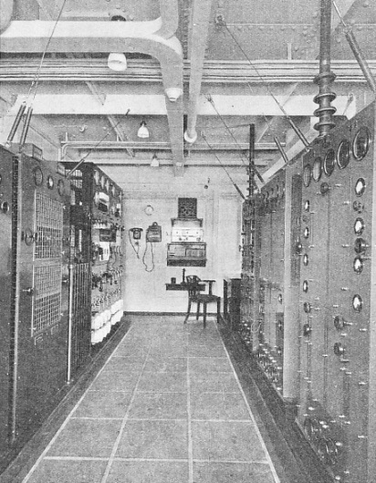 n installation of this kind, typical of thousands now in operation all over the world, is a powerful factor in the safety of life at sea. The evolution of the ship’s wireless set, from crude apparatus such as that in the Republic to the wonderful instruments in the liner of to-day, is the most spectacular stride ever made in maritime progress. Only about thirty years ago a ship, outward bound and “hull dow'n”, was in-a world of her own, bounded by the horizon. To-day she reaches out with impalpable fingers and keeps touch with the six continents and the Seven Seas.
A SHIP-TO-SHORE TELEPHONE installation. The three panels on the right contain the master oscillator, intermediate and final amplifier stages and modulating units. The feeder tubes to the aerial are on top of the units. Special coil springs are fitted to the tops of the panels to prevent vibration. On the left are the main switchboards and rectifying units.
You can read more on “Instruments of Navigation”, “Navigational Charts” and
“Romance of the Chronometer” this website.


