To conduct a ship safely across the high seas to a distant port calls for skill of the highest order and an intimate knowledge of the science of navigation. This chapter, written by a retired navigating officer of the Royal Navy, gives a clear account of the instruments required

A MODERN LINER’S CHART HOUSE. Located on the forebridge, the chart-house provides facilities for computing the ship’s course and position. Notice the long drawers for charts, the racks for pens and instruments, the repeater dials of various navigational and engine-room instruments and the indispensable telephone.
THE navigation of a ship is often a mysterious business to a landsman. If he is in a ship there is nothing to be seen except the ocean; yet day by day the ship speeds onwards, heading apparently straight as an arrow for some distant port perhaps thousands of miles away. Occasionally he may see one of the officers “shooting the sun” with an odd-looking instrument which, he learns, is a sextant - and whose connexion, if any, with the ship’s course is by no means obvious.
There is no other indication of how the ship is being navigated. He may be almost anywhere on the Seven Seas; yet day by day he finds, posted up, the ship’s exact noon-position, and the distance she still has to run before making port; and one day, exactly as predicted, they sight land and enter harbour, often within a few minutes of the time scheduled for their arrival. All this to the landsman is a great mystery. The methods and the instruments of navigation are, however, few and simple. Although they have been greatly developed in the course of time - especially during the last hundred years - they are identical in principle with those which came into use in the “Age of Great Discoveries”, the epoch (beginning about 1450) when navigators, no longer content with coasting timidly from headland to headland, began for the first time to undertake ocean-voyages.
To conduct a ship safely across the high seas to a distant port, the navigator requires first a chart, embracing his starting-point and his destination, on which he can lay off the course or courses which he must steer. He must also have some means of keeping his ship on her predetermined course, and some way of knowing what speed, at any time, she is making through the water. These two needs are met, respectively, by the compass and the log - not to be confused with the book of the same title in which the events of the voyage are recorded. Furthermore, while his ship is anywhere near the coast he must frequently determine, by the hand-lead or some equivalent, the depth of water in which he is navigating; and he must occasionally check her position by taking observations of recognizable points of land and plotting these “fixes” on his chart. Finally, when land is no longer in sight he must not trust to his “dead-reckoning” - that is to say, assume that because he has steered due W. (by compass) for 500 miles (by the log) he is necessarily 500 miles due W. from his starting point. By reason of tide, currents, bad steering and other sources of error, he may be quite a long way from his estimated position. He must therefore determine his latitude and longitude, as often as he can, by observations of the heavenly bodies, particularly the sun; and for this he requires a sextant, logarithmic tables, a Nautical Almanac and a chronometer. Such is an outline of his equipment: chart, compass, log and lead for all occasions; sextant and chronometer for use on the high seas. Give him these - he could get quite a workable set of them all into an ordinary kit-bag - and he will take his ship safely round the world.
There are, of course, many other instruments which, although not essential, contribute an additional factor of safety which no master of a large ship would reject. But the foregoing, which will be briefly described in turn, are the navigator’s everyday tools.
Let us describe first the chart, since this is the navigator’s primary requirement. The capacity to construct and use marine charts is not confined to civilized man. The Eskimo, for example, have long been noted for their skill in map-making; and the natives of the Marshall Islands (N.W. Pacific) have been accustomed, for centuries past, to construct lattice-work charts of palm-fibre, which indicate not only the various islands but also the direction of the prevailing winds and currents. In European waters seamen have used charts, of a sort, since the Middle Ages; and some charts of that period are surprisingly good - the Italian “portolani” charts of the Mediterranean (which were drawn by practical seamen) were far more accurate than the contemporary maps of that region produced by professional geographers. In general, however, charts of earlier date than 1770 or so are markedly defective in many respects. It was not until after Cook’s introduction of accurate methods into marine surveying, and the discovery of a practicable means of finding longitude at sea (the chronometer) that it became possible to produce a chart whose land-outlines, at least, if nothing else, agreed closely with reality.
Nowadays, almost every sea-Power publishes official charts of its own coasts; the principal maritime Powers go further and issue sets of charts embracing the whole world in detail. The British Admiralty publishes some 4,000 separate charts, of which about half relate to British territorial waters. The remainder are based on the charts of other nations (which, of course, no longer permit alien surveyors to work off their own coasts), but these charts are extensively adapted to conform to British usages. For example, in an Admiralty chart based on a French original the multitudinous soundings which the latter shows in metres would be converted into fathoms.
A chart differs from a map in being designed for use at some distance from the land, rather than upon it. Thus it devotes as much attention to the configuration and depth of the sea-bottom - generally left blank in most maps - as to the land itself.
Wrecked in Charted Waters
The outline of this, indeed, is shown with extreme accuracy, as are the positions of all conspicuous objects visible from seaward; but much of the inland detail is omitted. On the other hand, every care is taken to show not only off-lying islets and above-water rocks, but also every discoverable submerged rock, reef and shoal - matters concerning which an ordinary map would give no information whatever, and whose charting is only possible as the result of examination with the hand-lead, from boats.
This “sounding-out”, as it is called, is, perhaps, the most important portion of a marine survey; but there are many others. Unless the land-portions of the survey have already been mapped by the Ordnance Survey, or by some other authority of similar accuracy, they must be surveyed by triangulation - fixed marks being erected as necessary for this - and the topography must be connected to the triangulation and drawn in detail. Accurate astronomical observation for latitude and longitude must be taken. All portions of shallow water must be sounded-out so thoroughly as to give reasonable assurance that all dangers to navigation have been detected and located. How difficult this is to do may be judged by the fact that shortly before the war of 1914-1918 an uncharted rock was discovered in Portland Harbour, inside the break-waters, and in an area which had been sounded-out more than once. In 1922 the French super-Dreadnought France was lost when she struck an unknown rock, in the entrance to Quiberon Bay, which lay exactly on the line of approach indicated on the chart as recommended to vessels of deep draught.
At the same time, tidal observations must be made, and the range of the tide determined, for all soundings are reduced to the level of low-water spring tides, so that the navigator will almost always find a slightly greater depth of water, in any given position, than the chart indicates.
Even when the results of the survey have been reduced to chart form, and published, the navigator’s troubles are not over. Every chart is out of date before it is published. Incessant and inevitable change is the rule governing everything connected with the sea. Channels silt, or scour; new rocks and shoals are discovered, those already known change their depth and extent; buoys and lightships go adrift, or are moved to new positions; new lights, beacons and the like are established.
All such changes are, of course, notified by “Notices to Mariners”, but it is never possible to embody all of the most recent information in a chart before its publication; the most that can be done is to keep its users informed as far as possible, of all changes affecting it. Most nations, too, issue volumes of “Sailing Directions” which serve as a running commentary on their charts and contain much useful information for which no space is available on the charts themselves.
A feature of almost all charts, which stamps them at a glance, as differing from maps, is that they are generally drawn on Mercator’s Projection, in which all the meridians are parallel. This method involves a good deal of distortion: for example, in the figure of the world (shown below) Greenland appears almost as large as Africa, the area of which is, in fact, rather more than twelve times as great. But while this distortion renders Mercator’s Projection almost useless for maps, it is most valuable to the navigator. All the meridians being parallel, a line ruled from his starting-point to his destination cuts all of them at the same angle, and at once indicates a course which, if held throughout the voyage, will bring him to his port. On an ordinary map, whose meridians converge, such a line (which is termed a “rhumb line”) would be a complicated curve which could be drawn only with great difficulty.
 AS SHOWN ON MERCATOR’S PROJECTION")
THE WORLD (80° N. to 60° S.) AS SHOWN ON MERCATOR’S PROJECTION. The small dials above indicate local time corresponding, for every 30° of longitude, to noon at Greenwich.
Next comes the compass. The introduction of the magnetic compass was the greatest single advance ever effected in the art of navigation. The date of this introduction cannot be accurately fixed, but the compass was undoubtedly known to the European navigators of the twelfth century. That its use did not immediately become general is probably due to the suspicion of sorcery which this method entailed. In the early days of wooden ships the compass in its simplest form - a circular card marked out in “points” (spaces of 11¼° - 32 in all), carrying a needle-shaped bar-magnet and pivoted on a fine point - gave satisfactory service. The fact had long been known that, in general, it did not point to the true North, but to one side of it or the other (this angle, varying at different spots on the earth’s surface, being termed the “variation”), but allowance could be made for this without much difficulty. As a greater proportion of metal-work began to find its way into wooden ships, however, the compass’s indications grew less and less reliable; and in the closing years of the eighteenth century the gallant and unfortunate Capt. Matthew Flinders, R.N. - famous for his Australian surveys - drew attention to the fact that such metal-work produced in the compass a perceptible “deviation” which was not constant, but varied according to the direction of the ship’s head.
It was the rapid development of iron shipbuilding in the first half of the last century which really directed public attention to the defects of the magnetic compass. An iron ship, while being hammered on the stocks, becomes a permanent magnet - just as a poker can be magnetized by holding it roughly N. and S. and tapping it with a hammer. Apart from this “permanent” magnetism, the earth’s magnetic force induces temporary magnetism m the soft-iron portions of the hull, and this magnetism varies its amount in different parts of the world; so does the directive force which the earth exerts on the compass-needle - while the ship’s permanent magnetism remains unaltered. In fact, a magnetic compass in an iron or steel ship has about as much chance of a peaceful life as the proverbial “celluloid cat in hades” - and although most of the errors caused by permanent magnetism can be “ironed-out” by small permanent magnets placed in the binnacle (the compass-stand), and those due to induced magnetism by masses of soft-iron placed close to the compass, these corrections cannot be either complete or lasting.
That is why every ship, soon after launching and at intervals during her career, is “swung for adjustment of compasses” - that is to say, headed to each point of the compass in succession, while a bearing of some prominent object (whose magnetic bearing is known) is taken at each point. The difference, in each instance, between the compass-bearing and the magnetic bearing gives the “deviation” of the compass for that particular direction of the ship’s head; and these deviations are tabulated and applied whenever a course is set or a bearing observed.
Whatever pains were taken, adjusting the old pattern of magnetic compass in an iron ship was always a difficult business - in some instances it proved almost impossible. The famous Great Eastern, for example, had a compass-card a foot in diameter, with needles weighing several ounces, and to adjust this completely would have necessitated soft-iron correctors weighing several hundreds of tons.
In 1876, however, Sir William Thomson (afterwards Lord Kelvin) introduced a greatly-improved compass which was the forerunner of most modern types. Its card was a miracle of lightness and strength. It consisted of an aluminium rim, with spokes of fine thread, carrying a light paper disk and eight fine, short, magnetized needles. It was extraordinarily steady and easily corrected. Compasses of the Kelvin type are still largely employed, although for Naval purposes they have been superseded by the Chetwynd liquid compass, in which the compass card is surrounded on all sides by water. Such compasses are very steady, and resist the shock of gun-fire better than the Kelvin type.

AT INTERVALS DURING HER CAREER a ship is “swung for adjustment of compasses”. She is headed to each point of the compass in succession, while a bearing of some prominent object (whose magnetic bearing is known) is taken at each point. The difference in each instance between the compass bearing and the magnetic bearing gives the deviation of the compass for that particular direction of the ship’s head. These deviations are tabulated and applied whenever a course is set or a bearing taken. Swinging for adjustment of compasses is necessary because, although the “induced” and permanent magnetisms are corrected by magnets and soft iron, these corrections are neither complete nor lasting.
The last thirty years have seen the evolution of an entirely novel type of compass - one which, for use in steel ships, has outstanding advantages over any compass of the magnetic type.
Its inception is due to a German scientist, Dr. Anschutz-Kaempfe. Early this century Dr. Anschutz-Kaempfe, following Jules Verne and ante-dating Sir Hubert Wilkins, was planning an expedition which should reach the North Pole by submarine, under the ice-floes. He reasoned that when near the North Magnetic Pole the indications of a magnetic compass would be wildly erratic, and could not (while under the ice) be corrected by observations. He therefore turned his attention to the production of a compass which did not employ magnets. The task proved so fascinating - and so difficult - that he abandoned his projected expedition and devoted his attention to the new compass, which underwent its first sea-trials in 1907. These were promising enough to warrant further research. At the same time the attention of other inventors became directed to the same field. At the present day several types of gyro-compass - the Anschutz, Sperry, Brown, and others - are in extensive use all over the world.

A SHIP BEING STEERED AUTOMATICALLY by a gyro-compass and without any assistance from a helmsman. In the gyro-compass a heavy wheel running in perfect bearings is spun at high speed by an electric motor and mounted so that it is free to turn until its axle is in the meridian, pointing true north and south. It makes no difference how the axle is pointing when the motor is started up - it will slowly turn to the true North and South line and stay there. The gyro-compass is subject to slight deviations of approximately 1° caused by the speed of the ship. These deviations, however, can readily be allowed for; and its strong directive force, its ability to find and keep the true North and its insensibility to any magnetic influence has made the gyro-compass the perfect compass for a steel ship.
The theory of the gyro-compass is somewhat complicated - but its action is analogous to that of the toy gyroscope-tops with which most of us are familiar. Such a gyroscope, when spinning rapidly, opposes any force tending to turn it out of the plane in which it is rotating; and when such a force is applied the gyroscope does not turn in that direction, but in another at right angles to it. If, then, the force be applied vertically downwards, the gyroscope will begin to turn horizontally; and it will continue to do so until the force is either removed or opposed by another.
In the gyro-compass a heavy wheel running in perfect bearings is spun at high speed by an electric motor and mounted so that it is free to turn horizontally. Arrangements are made for a vertical force - that of gravity - to be exerted on the wheel; and the effect of this force, acting in conjunction with the earth’s rotation, causes the wheel to set itself so that its axle is as parallel with that of the earth itself as the restrictions of its mounting will permit. In other words, it turns until its axle is in the meridian - pointing true North and South. It makes no difference how the axle is pointing when the motor is started up - it will slowly turn to the true N. and S. line, and stay there. Also, its directive force is much greater than that of a magnetic compass; a single “master compass” can control, through electric circuits, a number of “repeater-compasses” located all over the ship and keep them “in step” with its own indications. Nor is this all - the gyrocompass can be employed to steer the ship automatically, without the intervention of a helmsman.

A STANDARD MAGNETIC COMPASS mounted in a binnacle. On top of the compass bowl is the “azimuth mirror” for taking bearings. The two large spheres are of soft iron and partly correct the ship’s “induced” magnetism. This induced magnetism is from the Earth’s magnetic force which causes temporary magnetism in the soft iron portions of the hull. In the binnacle itself are small permanent magnets, which counteract “permanent” magnetism. An iron ship, while being hammered on the stocks, becomes a permanent magnet just as a poker can be magnetized by holding it approximately N. and S. and tapping it with a hammer.
The gyro-compass is subject to slight deviations (of 1° or so) occasioned by the speed of the ship. These deviations, however, can readily be allowed for - and its strong directive force, its ability to find and keep the true North, and its utter insensibility to any magnetic influences make it the perfect compass for a steel ship. On the other hand, it is complicated, and its upkeep requires a certain amount of skilled attention. The difference between a ship with magnetic compasses and one with a gyro-compass installation is of the same kind as that between a house lit with oil-lamps and one with its own electric-light plant. The oil lamps are simple, self-contained and independent - a failure of one leaves the others unaffected. The electric light is infinitely more convenient - but a slight failure at any point may plunge the house into darkness. It will probably, therefore, be many years before the magnetic compass is entirely superseded, even in large vessels; but it will tend more and more to be pushed into the background by the gyro-compass, and to be regarded as a stand-by, rather than an essential.
The earliest method (except that of simple estimation) of determining how fast a ship is moving through the water was the “Dutchman's Log”. A piece of wood or an empty bottle was thrown over the bow, and the time of its passing along the ship’s side, and going clear of the stern, was noted. The ship’s length being known, her speed could be calculated. Oddly enough, this obviously rough method is still used (but with many additional refinements) when a ship is running her trials in the open sea, and a “measured mile” is therefore not available. The “Dutchman’s Log” gradually gave place to the “hand-log” - which, in sailing-ships, was perfectly satisfactory. A small float, shaped to offer considerable resistance to towage, and with a line attached, was thrown overboard - the line, which was marked at intervals by knots, being allowed to run out freely. After the lapse of a certain number of seconds (measured by a sand-glass) the line was held, and the number of knots which had run out noted. The distance between two knots (about 47 feet with a 28-sec. glass) bearing the same proportion to a nautical mile that the time of running-out the sand-glass did to an hour, the number of knots out gave the ship’s speed in nautical miles per hour. Hence the term “ knot”, meaning a speed of one nautical mile per hour. A knot is not a measure of distance. Many people who should know better speak of a ship as “steaming twenty knots per hour”. This is meaningless - or, if it means anything, it means “twenty nautical miles per hour per hour”. The correct expression is simply “steaming twenty knots”.

AN EARLY METHOD OF DETERMINING A SHIP’S SPEED was the hand log. A small float shaped to offer considerable resistance to towage and with a line attached was thrown overboard, the line - which was marked at intervals by knots - being allowed to run out freely. After a lapse of a certain number of seconds (measured by a sand glass) the line was held and the number of knots which had run out noted The distance between two knots (about 47 feet with a 28-second glass) bearing the same proportion to a nautical mile that the time of running-out the sand glass did to an hour, the number of knots out gave the ship’s speed in nautical miles per hour : hence the term knot, meaning a speed of one nautical mile per hour. The man in the foreground of this picture is holding up the reel of log line. The man in the centre is tending the line as it runs out, and the man on the left is watching the sand glass.
The hand-log was not well adapted for measuring high speeds, and it required several men to heave it. During the nineteenth century it was gradually superseded by the “patent log”, of which there are many varieties. In all, a small “rotor”, bearing oblique vanes, is towed astern of the ship; and its revolutions, as recorded by counter-gear, give a measure of the ship’s speed. In the earliest patterns the counter-gear and dials were housed in the rotor itself, which had therefore to be hauled on board before they could be read; but such were soon replaced by improved forms in which the counter-gear was fitted at the inboard end of the log-line, and could be read by inspection at any moment. In the most modern devices of the kind, the counter-gear is electrically connected to a “repeater-dial” on the bridge, so that it is no longer even necessary to send a hand aft to read the log. Towing a rotor is sometimes inconvenient, and unless the tow-line is long the disturbances set up by the ship’s screws may affect the log’s indications. Some modern forms of log, therefore, have their propelling apparatus projecting from the ship’s bottom near the “pivoting point” - the point round which she centres when altering course. In general, these are very accurate - but all types of log, and even different specimens of identical type, have their slight “personal errors”, which must be ascertained and taken into account.
 When navigating in shallow waters it is always necessary, even if they are well charted and one is reasonably sure of the ship’s position, to keep informed as to the depth of water underneath her. The simplest method of doing this is to use the “hand-lead” - which has persisted unchanged for centuries, and probably has still a long life before it. It is simply a lead plummet, weighing several pounds, to which a hemp line, marked in fathoms, is attached.
TO FIND THE DEPTH OF WATER under a ship when she is being navigated in shallow waters, the leadsman uses the hand-lead - a lead plummet to which is attached a hemp line marked in fathoms.
Standing in the “chains” - a small platform built out over the side - the leadsman swings the lead over his head and lets it fly forward, dropping into the water as far ahead as possible. Gathering in the slack of the line until this gradually comes vertical, he notes whether the lead is on the bottom or not, and how much line is out - then he calls, in a peculiar and traditional cadence, either the depth found or the fact that he has “No bottom at - fathoms”. The cadence, once learned, long remembered - hence the old story of the dug-out coastguardsman, once heard by a surprised officer-of-the-watch calling, in quite correct style, soundings which gave no information. On inquiry, the ancient mariner replied: “Well, I still knows the toon, sir, but I’ve clean forgot the words.”
The hand-lead is of little use when a ship is moving quickly, or if she is in depths of more than a few fathoms. Sir William Thomson conferred another boon upon seamen when he introduced, in 1877, his improved sounding-apparatus. In place of a hemp line, his machine uses thin piano-wire, coiled on a reel fitted with counter-gear and brakes; releasing the brakes allows the line to run out freely under the weight of the lead sinker; and a brass “feeler” pressed on the line enables the operator to put on the brakes as soon as the lead touches bottom. The ship’s speed being known, the amount of wire out gives a measure of the depth of water. This can also be determined more accurately by means of a glass tube, coated inside with a reddish compound, which is encased in a protective brass tube and clipped on to the wire just above the sinker. The upper end of the glass tube is sealed and the lower open. As the apparatus descends, the sea-water compresses the air trapped in the tube and makes its way up this for a certain distance (which varies, of course, with the depth), washing away the colouring matter as it does so. If the tube is placed against a graduated scale after the lead has been hauled in, it shows at a glance the depth in which bottom was struck. As with the hand-lead, a cavity in the base of the lead can be “armed” with tallow, and will, except with rock, bring up a specimen of the bottom, whose nature is often of value in determining the ship’s whereabouts. The Thomson pattern of sounding-machine has also been adapted for securing soundings (either for scientific purposes or when laying submarine cables) in several thousand fathoms. For such work it has long superseded the old “deep-sea lead” - an enlarged and ponderous form of the hand-lead which took most of the ship’s company to heave it.
The majority of soundings, outside harbour waters - in which the hand-lead is still much used - are taken by sounding-machines of the Thomson type; but a method has been developed recently which is already a serious rival, and which offers enormous possibilities. It is as accurate as the sounding-machine - it is far more rapid - and it uses neither wire nor lead.

A WIRE-SOUNDING MACHINE of the Thomson type. After sounding, the wire is wound in by an electric motor. Sir William Thomson, who invented the modern magnetic compass, conferred another boon on seamen when he introduced in 1878 his improved sounding apparatus. In place of the hemp line of the hand-lead his machine uses thin piano wire coiled on a reel fitted with counter gear and brakes : releasing the brakes allows the line to run out freely under the weight of the lead sinker, and a brass “feeler” pressed on the line enables the operator to put on the brakes as soon as the lead touches the bottom. The ship’s speed being known, the amount of wire out gives a measure of the depth of water.
An isolated attempt to produce such an instrument was made by Dr. C. W. Siemens, who devised his “bathometer” in 1876. It measured very small variations in the earth’s total attractive force, and could therefore be used to determine by inspection the actual depth of water under a ship. It was tried in H.M. Surveying Ship Fawn with fair success - but it was delicate and unreliable, and never came into general use.
The modern “echo-sounding” installation is quite free from these defects; it is reliable and extraordinarily accurate. Its principle is this: a transmitter, located in the ship’s hull, emits a sharp sound which travels to the bottom, is there reflected, and returns to the ship, being picked up on a sensitive hydrophone of the type used during the war of 1914-1918 to detect German U-boats by the noise of their propellers. The interval between the original sound and its echo being accurately measured, and the velocity of sound in water known, the depth can at once be obtained. One form of the apparatus can be operated from the ship’s bridge.

AN ECHO-SOUNDING MACHINE. A transmitter placed in the ship’s hull emits a sharp sound which travels to the bottom, is there reflected and returns to the ship, being picked up on a sensitive hydrophone.
Echo-sounding apparatus can be used in shallow water and in oceanic depths. For example, echo-soundings have been taken in the Thames estuary with an error of no more than 6 in. in 15 fathoms; and cable-ships have obtained accurate echo-soundings in depths of more than 3,000 fathoms. Most remarkable of all, perhaps, is the fact that sunken wrecks have been successfully located by echo-sounding, the slight diminution of the interval as the ship passed over the sunken hull being clearly marked. So far, the instruments described have been those used in coastal and deep-water navigation. The sextant - although it can be, and sometimes is, used to determine a ship’s position by observing angles between objects on shore - is primarily useful for work on the high seas: for fixing the ship’s position, by astronomical observations, when no land is in sight.
Such observations will not, of themselves, give the ship’s position. They will give only her latitude and her local time - the time of the meridian on which she happens to be. To determine her longitude, as will be seen later, she must also know the time of some standard meridian - for example, that of Greenwich. The difference of the two times gives her longitude. But the observations must come first - and to secure them is not easy.
The navigator cannot, as the astronomer does, refer his observations to the vertical - because, owing to the ship’s motion, he cannot use a plumb-line, or a mercury trough, or anything of that nature. Neither can he employ an astronomical telescope; except in the flattest of flat calms he could never hope to keep the object he was observing within its field of view. On the other hand, he generally has an excellent clear-cut horizon all round him during the day, and at twilight - the only period in which he can take observations of the stars, for they are invisible by day and the horizon equally so during the night.

LATITUDE AND LONGITUDE. Latitude is measured by the angle subtended at the earth’s centre between a point on a given parallel and the Equator. Longitude is measured by the similar angle between any given meridian and that of Greenwich.
The early ocean-navigators observed for latitude by measuring the angle between the horizon and the sun when this was on the meridian; i.e. due N. or S. of them, and at its highest for the day. From this observed angle, with the help of rough tables of the sun’s apparent motion northward and southward during the year, the navigators could compute the latitude they were in - for their longitude they had to depend on the“dead reckoning”. They observed the sun with a “cross-staff” - a wooden instrument that resembled a T-square with a sliding cross-piece - moving the slider until one end of it was in line with the sun and the other with the horizon, the end of the staff itself being held close to the eye. The “probable error” of latitude observations taken with the cross-staff was about 1°, or sixty geographical miles - in other words, the navigator’s observations might put him off the Thames estuary when in reality he was not far from Lowestoft.
To be an expert with-the cross-staff the navigator had to be trained to look two ways at once. In the seventeenth century the cross-staff was superseded, for solar observations, by the “back-staff”, invented by the celebrated English navigator John Davis. In using this the observer turned his back on the sun, and aimed his backstaff (which had sights like those of a rifle) at the horizon, while causing the shadow of a fixed pin forming part of the instrument to fall on the foresight. It could not be used for star observations, and had a probable error of at least ½°.
The cross-staff and backstaff reigned supreme until 1731, when the sextant was simultaneously re-discovered by John Hadley, of London, and Thomas Godfrey, of Philadelphia: “re-discovered”, because afterwards it was learnt that a precisely similar instrument had been invented by Sir Isaac Newton in 1699, although no account of it had ever been published.

A SEXTANT FITTED WITH OBSERVING TELESCOPE AND SHADES TO MITIGATE STRONG SUNLIGHT. The angles measured are read on the graduated arc by a small microscope. The sextant was rediscovered simultaneously by John Hadley, of London, and Thomas Godfrey, of Philadelphia. It cannot be said to have been discovered by these men, because afterwards it was learnt that a precisely similar instrument had been invented by Sir Isaac Newton in 1699, although no account of it had ever been published. In essentials Hadley’s sextant is substantially that of to-day.
In using the sextant the observer sights the sea-horizon through an aperture which is half-filled by a small mirror. A radial bar, traversing a graduated arc, carries a second small mirror at its pivoting-point. When measuring the angle between the horizon and a heavenly body (or, for that matter, between any two objects) one is viewed directly, and the other brought into the field of view by double reflection in the two mirrors, the radial bar being moved as necessary. The angle on the arc is then exactly one-half of that subtended between the objects. For convenience of reading, therefore, the graduations are made double their true value - e.g. the 50° point of the arc is marked “100°”. Thus the ordinary sextant - so called because its arc is roughly the sixth part of a circle (60°) - will measure angles up to 120°.
As Newton pointed out in an unpublished MS. description of his instrument, the double reflection ensures that, once the two objects have been brought into apparent coincidence, they will remain so in spite of any motion of the ship or the observer, appearing as if glued together. It is this most valuable property which makes the sextant the one instrument, above all others, for taking astronomical observations on board ship.
In essentials, Hadley’s sextant of 1731 is substantially that of to-day. Many improvements, of course, have been effected in it - the frame, originally wood, is now metal; a telescope has been added (a good observing sextant is fitted with a choice of two or three telescopes, suited to different classes of observations); and the range and accuracy of the instrument have been increased. With the modern sextant altitudes can be taken to the nearest 10" - the sixth part of a minute of arc, or 1/32400 of a right angle, corresponding to an error in latitude of less than 350 yards.
It seems unlikely that the present form of sextant - light, simple, portable and very accurate - will be superseded for many a decade. The only unsolved problem connected with its use is the provision of a marine “artificial horizon”, for use on board ship when the sun is shining but the horizon obscured by fog or mist. Many attempts have been made to do this, some with considerable success, but no instrument of the kind has yet been devised which is perfectly satisfactory; i.e. certain in its action without being unduly complicated.

“SHOOTING THE SUN”. Observing, with the sextant, the sun’s altitude above the sea horizon. Two small mirrors give the sextant a double reflection, and it is this most valuable property which makes the sextant the one instrument, above all others, for taking astronomical observations on board ship. It will be seen that the two men cover their own shadows. This is possible only at noon in the tropics when the sun is overhead.
Sometimes known as “The Sailor’s Bible”, the Nautical Almanac, published at the instance of the Admiralty, is a compendium of astronomical information originally intended (it first appeared in 1767) solely for the use of navigators. In course of time it came to contain not only all that they were ever likely to require, but also a great deal which it was morally certain they would never have any opportunity of using.
In recent years, therefore, it has appeared in two forms - an abridged version for use at sea, and a much more copious one which is designed chiefly for the benefit of astronomers. Several other nations issue similar almanacs - and the contents of all, including those of Great Britain, benefit by the ready collaboration of the various national observatories.
The Nautical Almanac contains an enormous amount of accurate information relating to the positions and astronomical elements of the heavenly bodies, calculated several years in advance. Originally a large staff of computers was employed on such work, but for some years past all computations required have been done mechanically.
Reward of £20,000
When dealing with the sextant, it was pointed out that a ship’s observations give only her latitude and her local time - that before she can determine her longitude she must also know Greenwich time, or that of some other known meridian. To do this, she must either determine Greenwich time by astronomical observations, or carry an accurate timekeeper which records it.
It is possible to find Greenwich time astronomically by the “method of lunar distances”, which involves measuring the angular distance between the moon and either the sun or a suitable star, and then performing a long and intricate process of calculation. But the errors involved multiply at an amazing rate - an error of only 1' in the observed angle means one of anything up to thirty geographical miles in the resulting longitude. The other plan, that of using a timekeeper or “chronometer”, is very simple in theory; but although first proposed in 1530 (by Gemma Frisius) it remained impracticable for over two centuries. The mechanical difficulties involved in the construction of a timekeeper accurate enough for navigation (one, that is, with a total error of not more than a second or so per day) are almost inconceivably formidable. Newton himself thought that they could never be overcome - and until the middle of the eighteenth century scientists in general, and such professional clockmakers as had tried their hand at making marine timekeepers, entirely agreed with him. In spite of a reward of £20,000 offered by Act of Parliament in 1714 for any method of finding a ship’s longitude within thirty geographical miles at the end of a six weeks’ voyage to the West Indies, the famous “problem of the longitude” seemed, as late as 1760, to be insoluble.
In the following year however, a chronometer was entered by John Harrison - neither a scientist nor a clockmaker, but a self-taught Yorkshire carpenter - in competition for the great reward, which, after two successful trials of his invention, in 1761 and 1765, was ultimately paid to him. His machine, which was the fourth of a series (all of them accurate marine timekeepers) was too complicated to be made in quantity at a reasonable price; but its success stimulated professional clockmakers to attack the problem once more. By 1795 or so the chronometer had almost assumed its present-day form.
The marine chronometer is essentially a large and accurate watch, mounted in “gimbals” so that it remains horizontal whatever the motion of the ship. Its mechanism is slightly more complicated than that of a watch and embodies various contrivances designed to remove, as far as possible all sources of error which might affect its rate of going. The accuracy of the modern chronometer is remarkable - a good one will keep time at sea with an error of not more than one second per week, corresponding to an error in longitude not exceeding a quarter of a mile; yet in spite of the care and skill which have been unstintedly lavished on the development of chronometers ever since Harrison’s time, the fact remains that, as a primary method of finding longitude at sea the chronometer is almost as out of date as the “method of lunar distances”. In these days of wireless telegraphy a ship can be more accurately navigated with the help of an inexpensive pocket-watch than she could have been, fifty years ago using the finest set of chronometers that could be bought for money.

THE MARINE CHRONOMETER is essentially a large and accurate watch mounted in “gimbals” so that it remains horizontal whatever the motion of the ship. Its mechanism is slightly more complicated than that of a watch and embodies various contrivances designed to remove as far as possible all sources of error. A good modern chronometer will keep time at sea with an error of not more than one second per week, corresponding to an error in longitude not exceeding a quarter of a mile.
All that the best chronometer can do is to carry the Greenwich time - with a slight, but unavoidable, risk of error - from a place where this is known to another (say, in mid-ocean) where it is not. Going with a slight but nearly uniform rate of gaining or losing, it enables the navigator to predict what, at any future date, its error on Greenwich time will then be - and by applying this error to the time shown by the chronometer, he then has the Greenwich time itself. But if he can obtain this direct by a wireless time-signal - as he can - the chronometer’s primary usefulness is obviously diminished almost to nothing. It seems probable that before long it will be almost as much of a mere “stand-by” as the magnetic compass or the hand-log.
Wireless telegraphy is, of course, immensely valuable to the navigator in other ways. For example, gale warnings, information as to changes in lights, buoys, and the like can always reach him instantaneously, wherever he is. Of more technical interest is the fact that by means of a direction finding set he can obtain, by day or night, and even in the thickest fog, bearings of distant wireless telegraphy stations. Plotting such bearings on his chart, he at once obtains his exact position.
In fact, of all the gifts which science - organized human knowledge - has bestowed on the harassed navigator, that conferred by wireless telegraphy seems unquestionably the greatest Yet it is only one among many modern developments most of which have been brought about by the insistent demand for safer navigation in faster and larger ships, and which, in sum, have rendered modern navigation “an art and a mystery” not only to landsmen, but also to the navigators of fifty years ago; yet we can imagine them asking the navigator of to-day, as Columbus might have asked Cook, and Hanno Columbus, “With all these vast improvements, how does it happen that any ship of your day ever goes ashore?”
Certainly the question seems, at first sight, difficult to answer. But the chances of the sea and the fact that all navigators are human - and therefore fallible - are two reasons why no mere perfection of instrumental equipment can ever of itself ensure a vessel’s safety.
The navigator chiefly uses his instruments to ascertain how far he really is from where he has computed that he ought to be. That he has perpetually to do this is due to the sea itself, which has a way of its own with a ship, and delights in deluding the navigator as to his true position.
Navigation is very easy in fine weather, in well-known, well - charted waters, properly buoyed and lit; but in bad weather, off imperfectly-charted shores, among currents of ever - changing strength and direction, it is a desperately difficult business.
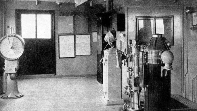
A VIEW OF THE BRIDGE of the M.S. Pilsudski. From left to right in this picture can be seen the engine-room telegraph and the echo-sounding machine, with steering repeater compass on top; between that and the magnetic steering compass in the foreground is the hand-steering column. The Pilsudski is a 14,400 tons twin screw vessel, owned by the Polish Transatlantic Shipping Co., and built in 1935.
You can read more on “The Modern Ship’s Wireless”, “Navigational Charts” and
“Romance of the Chronometer” this website.


