

© Shipping Wonders of the World 2012-

Building Marine Machinery
The engines that drive modern steamships or motorships must, despite their enormous size, be built with the accuracy and precision which characterize the most intricate and minute mechanisms
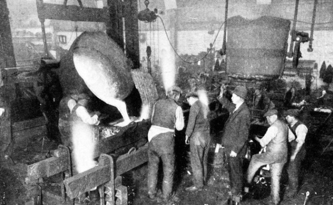
THE POURING OF MOLTEN METAL is among the most spectacular sights in a foundry for casting components of marine machinery. Molten iron is shown above being poured into a mould for a marine engine cylinder. After the pouring it takes many days for a casting to cool. When it is cool the casting is removed and prepared for machining.
TO the average man the most impressive feature of a marine engine is its size. Herein lies one of the most difficult problems faced by the builders of ships’ machinery. In the production, handling and machining of enormous castings and forgings the skill of the marine engineer is put to exacting tests. In addition the machinery that drives a ship or renders her innumerable services at sea must be within certain limits of weight and must be absolutely reliable.
The materials used must be of the best quality, ensured by repeated tests, and workmanship has to admit of no errors. The utmost precision must prevail in fashioning every component part.
It is on this high degree of accuracy that the safety of thousands of lives is dependent at sea. not only at the height of great storms, but also in fair weather when failure of steering gear or propeller shaft may spell disaster.
The dimension difficulty has been met by the builder of marine engines with the characteristic courage that dominates all who build ships or brave the seas in them. The erecting shop in which the modern marine engine first takes shape is of enormous size. It has to be, for in it are erected the complete sets of engines that will eventually be packed inside the hull of, perhaps, a mammoth liner. And even within the confined space of a liner’s hull there is room for a fair-
The machine shops adjoining the slipways of a shipbuilder’s yard are vast halls covering acres of ground. The shops are interlaced with railway lines for the supply of materials and the removal of a ship’s engines, either as complete sets or piecemeal, for subsequent re-
A marine engineering works is divided into a number of different departments, separate from one another, but all working in co-
It may assist if we consider first the building of engines for a large twin-
In the drawing office all the blueprints are prepared for use in the various shops. Here are prepared the designs for every part of the vast complication that is presented by a reciprocating marine engine. Here, too, is worked out the system of “packing” that ultimately will fill the ship’s machinery spaces with her power plant.
When the designers and draughtsmen have settled all points of detail the construction can begin. Work on the engines for one ship is carried out simultaneously in all departments so that there shall be no delay in the final erection of the engine.
The largest components of a marine reciprocating engine are the bed-
Special precautions, too, must be taken to ensure that the casting shall not crack in cooling or become distorted . It is partly for this reason that all thin portions of the casting are curved or “faired” into the thicker portions No sharp interior corners are permitted.
The mixing and testing of the various grades of iron used in marine castings are matters of great importance, especially where cylinders are concerned. A marine engine cylinder is subject to shock from the sudden admission and expulsion of steam, at high temperatures and to the wear of the piston.
Huge Cylinder Castings
Cast iron is often regarded as an exceedingly “solid” material. It is, however, capable of being stretched, and under hydraulic pressure water can be forced through it. A marine high-
Large castings in iron follow the same general practice, modified as required to suit the work in hand. The first process is the making of the patterns, generally of wood, that are used in the preparation of the sand mould to receive the molten metal. The patterns are made a little larger than the castings, to allow for the shrinkage of the metal on cooling. The casting is done on the floor of the foundry, where the patterns are lowered into pits and buried in large quantities of special moulding sand, a dark, earthy material that takes the impression of the surface against which it is rammed. The lower part of the pattern is impressed in the sand and the upper part is dealt with in a large open box, also containing sand, which is lowered over the pit or lower box.
Next are prepared “cores” of sand which are placed within the mould to prevent the flow of metal in the spaces they occupy and so form the bores and steam passage-
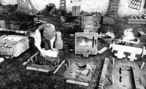
MOULDS IN THE DARK SAND that comprises the foundry floor. The moulder is resting his left hand on a pattern and is pointing to the pattern’s impression with his other hand. Behind him is a bottle-
The metal is melted in cupolas fired by solid fuel, oil or gas, and is run off into huge ladles for the final pouring. When the casting has cooled (a matter of several days) it is taken from the mould, cores are removed, and all surfaces are cleaned to get rid of the sand. Now follows the machining, a process that varies in the different marine engineering works. One widely adopted method is to use a machine tool known as a boring mill. This machine comprises a horizontal turn-
The turn-
The cylinders of a large steam reciprocating marine engine cannot be removed readily from the ship when they have become worn. To overcome this difficulty the bores are fitted with removable liners. These cylinder liners are of special cast iron, or of steel, and they can be replaced when worn by the action of the piston.
Marine pistons are of cast iron or, in the largest and fastest running engines, of steel, and are approximately cone-
A particularly important feature of piston construction lies in the method of its casting. The design must allow for the cooling of the metal without cracking. In the early days of cast marine engine pistons it was a fairly common occurrence to have a sudden engine breakdown at sea.
“Junk-
When a cylinder cover was removed the piston would be found grouped artistically round a bare piston rod — in a hundred pieces. The piston had become faulty during the cooling of the casting, with consequent failure at an inopportune moment.
Failure of this kind is now rare, especially where the casting has been done in steel. Piston castings are carefully machined in a lathe or vertical mill, a tapered hole is bored in the central boss for the piston rod, and a groove is turned in the working face for the piston rings. In a marine cylinder the piston rings perform the same function as their smaller counterparts in the motor-
The piston rings are of close-
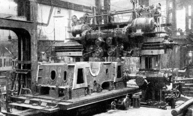
A MASSIVE CASTING IN A PLANO-
The columns that support the cylinders are usually of cast iron or cast steel. Or they may be made of wrought steel, with a flange at top and bottom for bolting to the cylinder and the engine foundation respectively. The design of these columns calls for great care. They are subject not only to the push-
Apart from the columns, there is another part of the engines that has to withstand stresses additional to the mechanical strains of their working. This is the bed-
Again cast iron or cast steel is used, and the casting is machined in a huge planing machine which prepares the seatings for the columns, main bearings and other parts of the engines. A planing machine comprises a rectangular table provided with X slots for bolting down the work. This table is driven backwards and forwards on a bed-
Cylinder and valve chest covers are cast and machined in a similar manner to pistons. Light steel castings are used for the crossheads that join the piston rods to their connecting rods and take the side thrust of the piston’s working stroke.
Components such as connecting and eccentric rods and the main crankshaft are forged from billets of solid steel. The giant of the forge is the mighty steam hammer that, can deliver a blow of enormous power or can accurately crack an eggshell with equal facility.
Giant of the Forge
The modern steam hammer, with its extremely accurate action, makes light work of the largest and most intricate crankshaft, whether for the steamer or for the great oil engines of a motor ship. Connecting rods and other components that are made by forging also come under the steam hammer in the initial stages of their manufacture, and their working surfaces are machined later.
Crankshafts for steam or oil engines are turned, after the preliminary forging, in huge lathes that machine the bearing journals and crank-
There is one auxiliary that is absolutely essential to the economical working of the marine steam engine, whether reciprocating or turbine. This is the condenser. Its construction has many points of interest, and although condensers show considerable variety in their size, shape and design, all have certain features in common. The body of the condenser may be a casting or a number of castings bolted together, or it may be built up of plates riveted together.
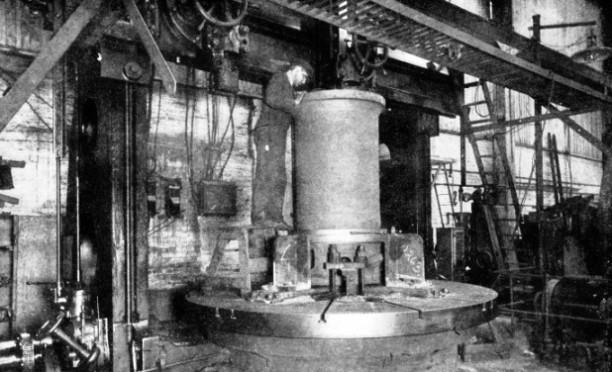
THE BORING MILL, with its enormous turn-
The plates into which the tubes are fitted are of brass or a similar non-
We have seen how the foundry, the forge machine and erecting shops all pool their efforts in the building of a reciprocating marine engine, whether steam or diesel. The methods adopted vary but little in either type of power unit.
The steam turbine, however, the action of which has been fully described in the chapter “Steam Turbine Engines”, calls for special comment on the method of its construction. A set of turbines usually comprises three separate cylinders or casings enclosing rotors for high, intermediate and low pressures respectively. The complicated castings for the upper and lower halves of the casings are made in a fashion similar to those of a marine engine cylinder. The high-
After they have been cast, the upper and lower casings are accurately machined. The grooves that will provide clearance for the moving blades, and those for the reception of fixed blades are bored out, and all flat jointing surfaces and seatings are planed. Turbine half-
Perfectly Balanced Rotors
Turbine rotors are forged from solid steel billets and then turned, with their hundreds of grooves, in huge lathes. The blades are usually formed out of solid bars by milling machines, in which the surplus metal is removed by revolving cutters. The blades may be of stainless steel, monel metal (an alloy of nickel and copper, with small quantities of iron and manganese) or of phosphor bronze. The greatest care is taken in fitting the blades, and the rotors are perfectly balanced so that, despite their size, they can be spun as easily as a child’s top. The modern turbine gear-
Modern marine boilers have features in their construction that are noteworthy. The marine boiler comprises a number of drums joined together by banks of tubes in a casing lined with firebrick. The steel tubes are made by forcing a solid white-
All boilers are tested by hydraulic pressure before they are put in steam, and a large factor of safety is insisted on by the Board of Trade before a boiler is passed for service.
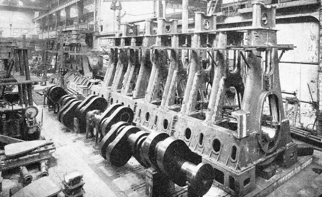
IN COURSE OF CONSTRUCTION in the works of the North Eastern Marine Engineering Co., Ltd., at Wallsend-
You can read more on “Building a Liner”, “Motor Engines” and
“The Queen Mary’s Engines” on this website.