The final form of the marine reciprocating engine was of the vertical type using steam in two, three or four stages of expansion
MARINE ENGINES AND THEIR STORY - 6
AMONG the finest horizontal trunk engines ever built were those installed in H.M.S. Northumberland, an iron sea-going armour-clad vessel designed by the Admiralty and built at Millwall Iron Works, London, in 1868. Her sister ship, H.M.S. Minotaur, was also equipped with trunk engines.
The engines of H.M.S. Northumberland had two cylinders 9 ft. 4 in. in diameter, with a stroke of 4 ft. 4 in. The trunks extended through the back and front covers of either cylinder. These trunks had a diameter of 3 ft. 5 in which reduced the effective areas of the pistons and made them equivalent only to those with a diameter of 8 ft. 8 in. The bearings or gudgeons carrying the small ends of the connecting rods were housed in the pistons, and the large ends of the rods drove balanced cranks set at right angles. These engines are illustrated in the previous chapter.
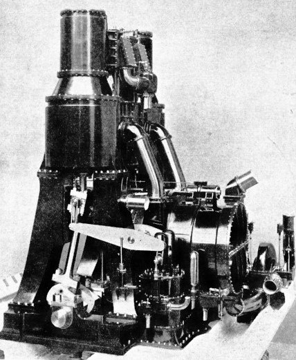
THE CONDENSER AND PUMPS of the engines of the Britannic of 1874 are shown in this photograph of a model. The engines were built by Maudslay, Sons and Field, and were 33 feet in height. They indicated a horse-power of 4,971 and drove a single screw giving an average speed of 13 knots on the Atlantic crossing.
The valve gear and method of steam distribution to the cylinders of these horizontal trunk engines is of special interest. The steam chest of each cylinder contained a large double-ported slide valve, worked by link motion reversing gear. These large slide valves were provided with circular relief frames on the back surfaces. A relief frame is a device designed to relieve a valve of part of the steam pressure on the back, thus lessening the friction between its face and the port faces over which it slides in the valve chest. Relief frames minimize the power required to move the slide valves in large steam-engines, but they have, to a certain extent, fallen into disuse since the introduction of the balanced piston valves used in modern practice.
In addition to the link motion valve gear, the engines of H.M.S. Northumberland were provided with large expansion valves to give an early steam cut-off. The additional valves were operated by separate eccentrics through links that permitted the cut-off to be varied. These valves were arranged above the steam chests and cut off the steam from the chests and the cylinders during each piston stroke. The link motion of the main slide valves then gave a second cut-off affecting the cylinders only.
The propeller was-of the Mangin type, 24 feet in diameter, with four blades capable of an adjustment of pitch between 22 ft. 6 in. and 28 ft. 6 in. The blades were set at a pitch of 25 ft. 6 in. Ten tubular boilers, each with four furnaces, supplied steam at a pressure of 25 lb. The total heating surface was 23,040 sq. ft. and the grate area was 956 sq. ft. The engines indicated 6,545 h.p. at 58½ revolutions a minute, giving a speed of just over 14 knots.
The inverted type of marine steam engine, with the cylinders arranged vertically over the crankshaft, was introduced about the year 1850. From about 1860 this form of reciprocating engine became standard practice for passenger and cargo vessels in the merchant service. In the Royal Navy, however, the vertical engine was not at first widely adopted except for a few coastal defence ships in 1872.
The reason for this slow progress in the Navy was the necessity for placing the machinery below the water-line. The need for this form of protection ceased after 1860 on the introduction of side armour for warships. It was not until 1875 that vertical engines were installed in battleships. The vertical engine was finally employed in all warships until it again became convenient to place the machinery below the water-line in the form of the steam turbine.
The advantages of the vertical engine over all earlier types include economy in athwartships space. Two sets of engines could be placed side by side in twin-screw steamers. Moreover, the length of the connecting rods was in no way restricted and the unequal wear of large pistons in horizontal cylinders was eliminated.
Vertical marine engines, in the early days of their development, were sometimes arranged to work as “simple” or single-stage expansion engines. Inverted vertical engines of the single-stage expansion type were installed in the Cadiz and Havana mail steamer A. Lopez, built and engined at Dumbarton in 1865. A fine working model of these engines, built to a scale of one-
fourth full size and developing about 15 horse-power, is preserved in the Science Museum at South Kensington.
The engines comprised two cylinders 5 ft. 6 in. in diameter, with a stroke of 3 ft. 6 in. They drove cranks set at right angles. Each piston had two rods terminating in a long crosshead working between guides. By adopting this method of construction, the total height of the engines was reduced.
The slide valves controlling the steam supply to the cylinders were operated by link motion reversing gear. The links were moved as required by large handwheels from a driving platform built round the engines at approximately middle-height. The link motion controlled the steam admission and exhaust and in addition a cut-off plate was provided. The function of this plate was to provide an independent steam control to permit of any required degree of expansion. The cut-off plate was placed at the back of the main slide valve in each steam chest and was in either instance worked by a separate eccentric. To reduce friction, the main slides were fitted with relief frames.
An ingenious device was employed to counterbalance the weight of the main slide valves. To the upper ends of the valve rods were attached pistons that worked in cylinders placed on top of the steam chests. Steam from the chests acted on the undersides of the pistons, thus supporting the weight of the slides and lessening valve motion strain.
Another point of interest in the design of these engines was the unusual position of the condenser. This was of the surface type, with horizontal tubes giving 3,488 sq. ft. of cooling area. The condenser was placed between the two engines, forming part of the framework that supported the two cylinders. At the ends of the engine were turned steel columns supporting the cylinders and steam chests. At either end of the condenser were arranged the air, circulating, feed-water and bilge pumps, all in duplicate and driven by rods from the crossheads.
Early Compound Engines
The arrangement of the pumps and their valves was of special interest. The feed and bilge pumps had simple plungers, but the others were provided with pistons working in cylinders. The portions of the cylinders above the pistons acted as air pumps and those below the pistons served as circulating pumps for the supply of cooling water to the condenser. Valve boxes for the pumps were arranged within the condenser, but the valves, of the rubber-disk type on removable grids, were accessible through doors in the condenser casing.
 Sea-water entered the circulating pumps through two pipes in the engine bed-plate, passed through the condenser tubes and was discharged overboard through a lagged pipe. The exhaust steam passed through jackets round the cylinders to the top of the condenser. The condensed steam, collecting in a hot well in the base of the condenser, was pumped back into the boilers.
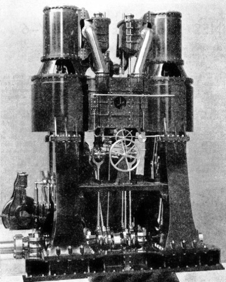
THE TANDEM COMPOUND ENGINES of the Britannic, built in 1874. This photograph shows the control side of the model illustrated above. The engines comprised two low-pressure cylinders, of 6 ft. 11 in. diameter, and two high-pressure cylinders with a diameter of 4 feet.
These engines indicated 1,427 horsepower at 45½ revolutions a minute, with steam at a pressure of 18 lb. per sq. in., giving a speed of over 13 knots. The A. Lopez had a displacement of 2,665 tons and was 270 feet long with a beam of 38 feet.
Following on “simple” engines of the type described above, came compound or two-stage expansion vertical engines. Among early compound marine engines of the inverted vertical type were those installed by Humphrys and Tennant in the P. & O. liner Carnatic, in 1863. This vessel, built by Samuda Brothers at Poplar, had a displacement of 2,800 tons. She was 235 feet long between perpendiculars and had a beam of 38 feet. The design of these engines is of special interest in view of the early date at which they were built. It is stated that steam was used at a pressure of only 26 lb. per sq. in. The steam was superheated, however, in copper superheaters before entering the cylinders.
The end standards of the engines of the Carnatic contained the surface condensers. These supported the two low-pressure cylinders, 8 feet in diameter, and bolted together in a fore-and-aft position. The high-pressure cylinders, 3 ft. 7 in. in diameter, were arranged tandem-fashion on top of the low-pressure cylinders. The common stroke of the cylinders was 3 feet. The cylinders were steam-jacketed and all were provided with slide valves, but there were only two sets of link motion reversing gear. The weight of each pair of slide valves was counterbalanced by weighted levers, an interesting contrast with the piston and steam cylinder method employed in the engines of the A. Lopez.
The air pumps were combined with the boiler-feed pumps and were worked by rods from the low-pressure pistons. Cooling water for the condenser was circulated by a centrifugal pump driven by a separate engine. Somewhat similar, but much larger, tandem compound engines were fitted in the White Star liner Britannic. This vessel was built of iron at Belfast by Harland and Wolff in 1874. The engines were by Maudslay, Sons and Field, and comprised two low-pressure cylinders with a diameter of 6 ft. 11 in. surmounted by two high-pressure cylinders, 4 feet in diameter. The common stroke was 5 feet. Each of the low-pressure cylinders was bolted to the top of a pair of massive standards 14 feet high. They were also secured to one another with the valve chests in between. Separating the low-pressure cylinders from the high-pressure cylinders above them were hollow cone-shaped distance pieces, provided with openings that gave access to the intermediate stuffing glands. The total height of the engines of the Britannic was 33 feet, and the cylinder standards were bolted to a bed-plate more than 24 feet long.
The slide valves of each pair of cylinders were moved by a single valve rod operated by link motion reversing gear. This motion was fitted with a handwheel and screw for reversing, assisted by a steam cylinder. The power reverse was rendered necessary by the massive proportions of the component parts. On the back of every high-pressure slide valve was an expansion valve worked by a separate eccentric. The cut-off of the expansion valves could be adjusted simultaneously.
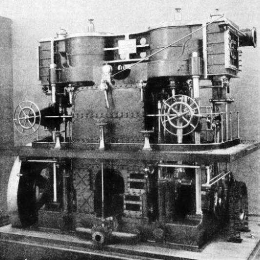
INVERTED SINGLE-STAGE EXPANSION engines were installed in the Cadiz and Havana mail steamer A. Lopez, built and engined at Dumbarton in 1865. This photograph shows a working model of these engines in the Science Museum. The model is one-quarter full size. It develops about 15 horse-power, and drives other models in the museum. For this reason a chain drive and fly-wheel have been incorporated in the model.
The two low-pressure cylinders exhausted into a single surface condenser, cylindrical in shape and placed at the side of the engines. The cooling water for the condenser was circulated by a centrifugal pump. This was driven by a pair of vertical cylinder engines placed on either side of the pump rotor casing. Two vertical air pumps and duplicate boiler-feed pumps were driven by levers from the crossheads. The steam and exhaust pipes of the engines were of copper and had special expansion joints to give flexibility under changes in temperature - an important consideration. Steam was supplied by a battery of eight boilers at a pressure of 70 lb. per sq. in. The boilers were of oval section, fired at either end, and contained 2,423 tubes. The total heating surface was 19,500 sq. ft. The engines indicated 4.971 horse-power and drove a single screw, 23 ft. 6 in. in diameter, giving an average speed of 13 knots on the Atlantic crossing.
The after part of the propeller shaft was originally provided with a universal joint so that, it could be lowered with the propeller boss level with the ship’s keel. This arrangement was introduced by Sir E. J. Harland in 1871, to secure greater immersion and so prevent “racing”, or excessive speed of the screw. Racing occurs when a ship’s propeller is lifted from the water by the pitching of the vessel in heavy weather. Sir E. J. Harland’s device affords an interesting comparison with Edward Shorter’s screw of 1800, described in an earlier chapter dealing with marine propellers.
The Britannic had a net tonnage of 3,152 (5,004 tons gross). She was 455 feet long, with a beam of 45 ft. 3 in. and a depth to the main deck of 33 ft. 8 in.
The next step in the development of the marine engine was the introduction of three-stage or triple-expansion working. In 1874 a Liverpool shipowner, Mr. W. H. Dixon, decided to employ three-stage expansion in his screw-steamer Propontis. To obtain maximum fuel economy, a pressure of 150 lb. per sq. in. was decided upon and the ship was fitted with new triple-expansion engines by John Elder and Co. The engines were designed by Mr. A. C. Kirk, and were the first triple-expansion engines installed in a sea-going vessel. The three inverted vertical cylinders were of the following diameters: high pressure, 1 ft. 11 in.; intermediate, 3 ft. 5 in.; low-pressure, 5 ft. 2 in. The common stroke was 3 ft. 6 in. Within a few years of its introduction the triple-expansion marine engine reached a remarkable degree of efficiency.
Overlapping Screws
Triple-expansion engines attained large dimensions when used in big passenger liners. Notable examples were those installed in the Majestic and her sister ship the Teutonic. These vessels were built and engined by Harland and Wolff in 1889 for the White Star Line. They were the first vessels of that company’s fleet in which sail power was finally abandoned.
Two sets of triple-expansion engines were installed in the Majestic, driving twin screws with a diameter of 19 ft. 6 in. and a pitch of 29 ft. 6 in. The propeller shafts were close together so that the screws overlapped by a distance of 5 ft. 6 in. It was necessary therefore to place the starboard propeller six feet astern of the other and to provide an opening in the ship’s “deadwood” to
give the required clearance between hull and screws. The diameters of the high-pressure, intermediate- and low-pressure cylinders were 3 ft. 7 in., 5 ft. 8 in. and 9 ft. 2 in. respectively. The stroke of all the cylinders was 5 feet. Apart from the size of the cylinders, the massive proportions of these engines may be gauged from the dimensions of the crank pins: 22 in. by 22 in.
Steam at a pressure of 180 lb. per sq. in. was supplied by twelve double-ended and four single-ended boilers, with a total heating surface of 40,968 sq. ft. The grate area was 1,160 sq. ft. These engines indicated 17,000 horsepower and drove the Majestic at a speed of 19½ knots. The displacement of the vessel (loaded) was 17,000 tons. Her overall length was 582 feet and her extreme beam was 57 ft. 10 in.
For use in the Navy the triple-expansion engine was widely adopted after the developments in protective armour. This type of engine was superseded later by the steam turbine. Noteworthy twin-screw triple-expansion engines were fitted in H.M.S. Duncan. At the time of her building she was the fastest battleship in the Royal Navy. She was built by the Thames Ironworks Shipbuilding and Engineering Co. in 1900.
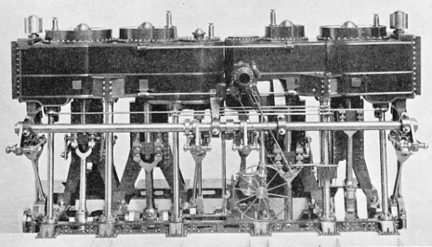
TRIPLE-EXPANSION ENGINES were fitted in H.M.S. Duncan, built in 1900. There were four cylinders in each set of her engines. The engines developed 18,030 horse-power at 120 revolutions a minute and drove H.M.S. Duncan by twin screws at a speed of 19 knots.
There were six ships of her class. The machinery was of less weight per horse-power than any previous battleship engines, resembling that usually fitted at that time in cruisers. There were four cylinders in each set of engines, with the high- and inter-mediate-pressure cylinders in the middle and a low-pressure cylinder at either end. Their dimensions were 2 ft. 9½ in., 4 ft. 6½ in., and 5 ft. 3 in. respectively, all with a stroke of 4 feet. The high- and intermediate-pressure steam was controlled by piston valves, and flat slides were used in the valve chests of the low-pressure cylinders. The valves were operated by Stephenson’s link motion reversing gear.
The starting platforms were placed beside the central fore-and-aft bulkhead. Steam was supplied at 300 lb. per sq. in. by twenty-four Belleville water-tube boilers. This pressure was reduced to 250 lb. per sq. in. at the engines. The boilers were fitted with economizers to heat the feed water. The engines developed 18,000 horse-power at 120 revolutions a minute, driving the ship at a speed of 19 knots. H.M.S. Duncan was well equipped with auxiliary machinery. She had evaporators and distillers for the supply of fresh water, two steering engines, four sets of combined engines and dynamos for the generation of electricity, refrigerating machinery, four sets of air compressors and other pumps. The ship was 405 feet long between perpendiculars, with a beam of 75 ft. 6 in. and a displacement of 14,000 tons. The final development of the reciprocating engine did not stop at triple-expansion working. Four stages of expansion have been in use for many years and are now combined with a high degree of superheating for the steam and special valves controlling its supply to the cylinders.
The introduction of four-cylinder quadruple-expansion engines dates back for many years. The earliest engines of this type were used to replace two-crank compound engines where additional power and economy were required, without the allocation of additional machinery space in the ship. The Suez, built in 1874, provides an instance of this practice. This ship, of 1,390 tons register, was originally fitted with compound engines. In 1887 they were replaced by quadruple-expansion engines built by the Central Marine Engineering Co. The new engines of the Suez comprised two pairs of tandem cylinders. The high-pressure cylinder and the first intermediate-pressure cylinder were at the top, with the second intermediate-pressure and low-pressure cylinders
respectively below them. The diameters of the cylinders were 1 ft. 10 in., 2 ft. 6 in., 3 ft. 7 in. and 5 feet. Their common stroke was 3 ft. 9 in. With steam at a pressure of 160 lb. per sq. in. these engines indicated 986 horse-power at fifty-six revolutions a minute.
The modern quadruple-expansion engine is built with the cylinders in line, in a fore-and-aft position. The two cylinders using steam of highest pressure were often placed at the ends of the engines. This arrangement was employed in the engines built by the North Eastern Marine Engineering Co. for the Well Line steamer Springwell. The diameters of the cylinders were as follows: high-pressure 2 ft. 11 in., low-pressure 6 ft. 4 in., second intermediate-pressure, 4 ft. 4½-in., and first intermediate-pressure cylinder 3 feet. The stroke was 4 ft. 6 in. The high-pressure and first intermediate-pressure cylinders were provided with piston valves, the others with slide valves.
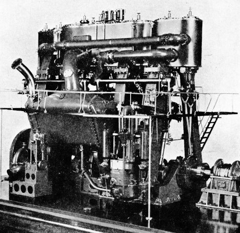
QUADRUPLE-EXPANSION ENGINES were built in 1914 for the Well Line steamship Springwell by the North-Eastern Marine Engineering Company. These engines indicated 4,400 horsepower at eighty revolutions a minute, with a steam pressure of 220 lb. to the square inch. This photograph illustrates a model in the Science Museum, South Kensington, and shows the surface condenser and the pumps at the back of the engine.
The surface condenser was placed at the back of the engine and was supplied with cooling water by a separately driven centrifugal pump. The air, feed and bilge pumps were worked by levers from the crosshead of the first intermediate-pressure cylinder. Steam-driven and hand-operated reversing gear was fitted and a steam “turning” engine was provided to move the crankshaft and motion for overhaul when in port. With steam at 220 lb. per sq. in. the engines developed 4,400 indicated horse-power at eighty revolutions a minute.
An interesting development was the introduction of double-beat poppet valves for the high- and intermediate-pressure cylinders.
In a later chapter will be described the development of the steam turbine.
You can read more on “Oscillating Paddle Engines”, “Propelling the Modern Ship” and
“The Queen Mary's Engines” on this website.


 Sea-
Sea-

