The limitation of space in early steamships led to the introduction of many ingenious arrangements in their machinery. Important among these were the famous trunk engines that once drove Great Britain’s warships and were in themselves fine examples of marine engineering
MARINE ENGINES AND THEIR STORY - 5

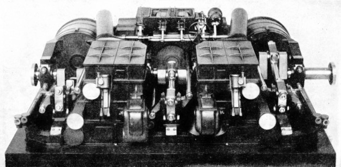
THE GEARED ENGINES of the famous Great Britain, built at Bristol in 1839-43. She was the first large iron ship and the first screw-propelled steamer to cross the Atlantic Ocean. Her engines had four cylinders with a diameter of 7 ft. 4 in. and a stroke of 6 feet. They had an indicated horse-power of 2,000, and drove the Great Britain at a speed of 12 knots. In the model shown the screw is placed close to the engines for demonstration purposes.
AMONG the earliest geared engines were those of the famous iron steamship Great Britain, the first screw steamer to cross the Atlantic. The Great Britain, designed by I. K. Brunel, was laid down at Bristol in 1839. She was launched in July 1843 and her trials were run in December 1844. On July 26, 1845, she left Liverpool for New York. The passage out took fifteen days at an average speed of more than nine knots. The return journey was accomplished in fourteen days. Two fine models of the Great Britain and of her propelling machinery are to be seen in the Science Museum at South Kensington.
The original engines of this ship consisted of four direct-acting cylinders, with a diameter of 7 ft. 4 in. and a stroke of 6 feet. The engines were placed low down in the ship and were inclined upwards to drive on to an overhead crankshaft. The cylinders were arranged in pairs that drove an overhanging crankpin and rested on cast-iron base plates. These plates were bolted to girders riveted to the ship’s frames. The overhead crankshaft was carried in bearings supported by two massive A-frames of timber and iron plates bolted to the ship’s beams at the level of the decks.
On-the crankshaft, between the A-frames, was secured a drum 18-ft. 3 in. in diameter and 38 in. wide. This drum drove another drum, 6 feet in diameter, on the propeller shaft beneath it by four sets of chains, weighing 7 tons. These massive chains were provided on the under sides with teeth that engaged with teak and lignum vitae blocks on the drums. The gearing was so proportioned that the propeller shaft made fifty-three revolutions to eighteen revolutions of the crankshaft.
The valves controlling steam distribution to the cylinders were of the piston type, 20 in. in diameter and operated by single loose eccentrics. These were fitted with toothed rims so that they could be revolved by manually-operated worm wheels for reversing the engines.
The wrought-iron condensers in the Great Britain were 12 feet long, 8 feet wide and 5 feet deep. They were placed amidships between the cylinders. The air pumps, 3 ft. 9½ in. in diameter with a stroke of 6 feet, were housed in the condensers and driven from the main crank pins. Levers attached to the air-pump crossheads worked the bilge and boiler feed-water pumps.
The propeller shaft of the Great Britain was in three sections and provides an interesting contrast with the multi-sectioned shafting in a modern liner. The first shaft section carried the lower chain drum and was 28 ft. 3 in. long. It had a diameter of 16 in. The middle section was 61 ft. 7 in. long with a diameter of 30 in. This section was hollow, built-up of two thicknesses of boiler plate held together by countersunk rivets. The third length of shafting carried the propeller and was 25 ft. 6 in. in length, with a diameter of 17 in. at the bearing journals.
After many experiments the Great Britain was fitted with a six-bladed propeller, 15 ft. 6 in. in diameter, with blades 6 in. thick and a pitch of 25 feet. This pitch meant that the screw should advance 25 feet for each revolution in the water. In practice the advance of the screw is less than the pitch because of “slip” and other factors. The propeller was not cast but was built up of plates riveted together. Later the six-bladed propeller broke and was replaced by a propeller with four blades.
The thrust from a ship’s propeller as it drives the vessel through the water is considerable. In the Great Britain the bearing that took this thrust consisted merely of a steel plate, 2 feet in diameter, against which pressed a gunmetal plate of the same diameter attached to the end of the shaft. The bearing was lubricated by a stream of water.
The engines of the Great Britain had a nominal horse-power of 1,000, but at 18 revolutions a minute with a boiler pressure of 5 lb. per sq. in. they had an indicated horse-power of nearly 2,000, giving a speed of 12 knots. The boiler was double-ended and consisted of a large shell 34 feet long, 31 feet wide and 21 ft. 7 in. high. It had a rounded top and was divided longitudinally into three separate compartments, each with eight furnaces, four at the forward end and four aft. The total grate area was 360 sq. ft. The furnace gases were led to a funnel, 8 feet in diameter, around the base of which was placed a feed water heater. The Great Britain was 289 feet long, 50 ft. 6 in. in beam, and 32 ft. 6 in. deep, with a draught of 18 feet. Her displacement was 3,618 tons.
In 1847 the original engines of the Great Britain were replaced by oscillating engines built by John Penn of Greenwich. These engines drove the propeller shaft through toothed gearing of particularly interesting design. Four pairs of wheels and pinions were used, placed side by side. The teeth of the wheels were not, however, arranged in straight lines, but were advanced successively a quarter of a tooth, thus making a staggered formation. This type of construction gave smooth running in operation, and strength was ensured by making all four wheels in one piece. A similar method was adopted in constructing the pinions.
Screw-propelled Warships
Gearing of this type was. frequently used in other steamers and a notable example was the power transmission system of the steamer Simla, built in 1854. This vessel was one of the first P. & O. steamers to be fitted with a screw propeller. The gear ratio was 1 to 2¾ and the large wheel had mortised hardwood teeth meshing with a cast iron pinion on the propeller shaft. The engines were of the “steeple” type with two cylinders. Each cylinder was provided with four piston rods terminating in a crosshead from which a connecting rod descended to the crankshaft below.
Screw propulsion had, from the outset, features of special interest to the designers of warships. In 1842, a small iron steamer, the Mermaid, of 164 tons, was bought by the British Admiralty for experimental purposes and renamed H.M.S. Dwarf. In the following year H.M. sloop Rattler was built by the Admiralty and she was the first screw-propelled vessel built for the British Navy. Her engines, of Maudslay’s “Siamese” type, drove the propeller shaft through gearing with three rows of teeth and a ratio of four to one.
It was in 1842 also that John Ericsson again made a contribution to marine engine history by introducing screw machinery for the first time below the water-line of a ship. Ericsson’s engines, installed in the United States warship Princeton, were of unusual design and of a type originally invented by James Watt. Cylinders were dispensed with and in their place segment-shaped chambers were used. The pistons were rectangles that swung on bearings as a door swings on its hinges. The piston hinge or bearing was carried outside the chamber and worked the propeller shaft by vibrating cranks and connecting rods, without the intervention of gearing.

RETURN CONNECTING ROD ENGINES were installed in H.M.S. Agincourt, a battleship built in 1863. The steam-jacketed cylinders were 7 ft. 7 in. in diameter and had a stroke of 4 ft. 6 in. The two large wheels on the platform control the reversing gear. Beneath the platform are the two massive crossheads with their twin piston rods. Flanking the platform are the condensers containing the horizontal air-pumps. The engines indicated 6,667 horse-power.
An interesting type of direct-acting machinery was installed in the screw steamer Harbinger. This vessel was built of iron by C. J. Mare & Co., of Blackwall, in 1851, and was employed in the East Indian and Cape mail service. She was of 599 tons register with a gross tonnage of 848. Her length between perpendiculars was 186 ft. 6 in., with an extreme breadth of 31 feet and 19 ft. 3 in. depth of hold. Her engines, built by Maudslay, Sons and Field, had two cylinders 41½ in. in diameter with a stroke of 27 in. The cylinders were arranged on opposite sides of the propeller shaft.
The cylinders were placed so that they drove diagonally upwards on to a single crank. The steam chests were on top of the cylinders and each contained two slide valves operated through rocking shafts by eccentrics. The condenser, situated beneath the crankshaft and between the cylinders, formed part of the engine bedplate and contained a vertical air-pump driven by a separate outside crank. The bilge and feed pumps, arranged alongside the cylinders, were also driven from this crank, which had a shorter throw than the main crank. Tubular boilers supplied steam at a pressure of 15 lb., and the engines were driven at a speed of 26½ revolutions a minute. Many other vessels were fitted with this type of engine between 1848 and 1852.
John Ericsson, after his invention of an efficient screw propeller, left England for the United States. In 1843 Ericsson’s European representative, Count de Rosen, fitted a direct-acting engine of the “return connecting rod” type in the French frigate Pomone. This engine resembled the “steeple” type used in paddle ships and was arranged horizontally. It was the first direct-acting horizontal screw engine. The kiteshaped “loop” of the steeple engine (referred to in an earlier chapter) was employed, but two piston rods were used instead of one and the weight of the loop frame was carried on a slide.
A return connecting rod engine was fitted in H.M. frigate Amphion in 1844. This type was much used in the British Navy for more than thirty years. H.M.S. Amphion’s engines had two cylinders arranged on opposite sides of the crankshaft which was spanned by the twin rods of the pistons. The piston rods terminated in a crosshead from which a connecting rod “returned” to the crank. The symmetrical arrangement of the cylinders was not always adhered to, and many engines of this type were built with the cylinders on one side of the crankshaft.

DIRECT-ACTING ENGINES with inclined cylinders driving upwards were fitted in the screw steamer Harbinger, built of iron in 1851. The cylinders were 3 ft. 5½ in. in diameter with a stroke of 2 ft. 3 in. The condenser was beneath the crankshaft and formed part of the engine bed. Many other vessels were fitted with engines of this type between 1848 and 1852.
These horizontal engines presented a splendid spectacle as the rods thrust in and out of the cylinders. Brightly polished cranks flashed as they turned under the drive of the massive connecting rods, and the wonderful array of pump levers and other moving parts gave a fine impression of power and dependability.
Among the wonderful models in the Science Museum at South Kensington are some of special interest. These models, constructed to a scale of one-twelfth full size, represent the horizontal engines fitted in H.M.S. Agincourt, in H.M.S. Boadicea and in H.M.S. Bacchante. The models are shown working at slow speed so that their action can readily be observed.
H.M.S. Agincourt was a battleship built at Birkenhead by Laird Brothers in 1868. Her return connecting rod engines, built by Maudslay, Sons and Field, exhibited many unusual features. The two cylinders of her engines were steam-jacketed to minimize the effects of condensation. There were several stuffing glands, and the nuts of each were connected by worm gearing, thus reducing friction by ensuring alinement on tightening up. The valve gear was of the link reversing type controlled by screw gearing and the links were supported by weights on counterbalancing levers.

ANNULAR ENGINES, adapted from the type patented by Joseph Maudslay in 1841, were installed in the steam yacht Hebe in 1856. Either of the two vertical cylinders contained a central trunk, through which passed a connecting rod from the crankshaft to the crosshead moving in the four-columned guides shown above. The two eccentrics and curved link of the reversing gear can be seen beneath the valve chest at the left of the illustration.
A steam expansion valve was fitted to every cylinder. These valves were of the cylindrical revolving pattern designed by J. Field. They were attached to the valve chest at its junction with the main steam-pipe. Steam could thus be cut off independently of the link motion and the volume of the valve chest was temporarily added to that of the cylinder. The expansion valves were driven at the same speed as the crankshaft by spur gearing. A sliding sleeve with a helical groove was provided so that the point of steam cut-off could be altered. The expansion gear could also be disengaged by a clutch.
Two jet condensers were placed opposite the cylinders with two horizontal double-acting air-pumps driven directly by separate rods from the pistons. Between the air-pumps were the crosshead guides and over these, between the condensers, was the driving platform equipped with two large handwheels for reversing and controlling the machinery.
Multi-stage Expansion Engines
The engines of H.M.S. Agincourt developed 6,667 indicated horse-power, giving her a speed of 15½ knots. The ship was of 10,600 tons displacement and measured 400 feet in length, with an extreme breadth of 59 ft. 5 in. and a draught of 27 ft. 9 in.
The unarmoured corvettes H.M.S. Boadicea and her sister ship H.M.S. Bacchante were built at Portsmouth in 1875-76 and fitted with engines of similar design. These were of the return connecting rod type, but had three cylinders instead of the more usual two. They were also designed for compound or two-stage expansion working. The high-pressure cylinder was 6 ft. 1 in. in diameter and the two low-pressure cylinders were 7 ft. 8 in. in diameter, all with a stroke of 4 feet. The cylinders were fitted with steam jackets on the barrels and on the ends.
The weight of the pistons was considerable and, to prevent undue wear on the lower surface of the cylinder bore, an ingenious sliding arrangement was adopted. Every piston was provided with a plunger at the lowest part of its circumference and this slid backwards and forwards on an adjustable bearing block. The back cover of every cylinder was provided with a projecting “bonnet” to clear the plunger of the piston. The usual twin piston rods were fitted, with the crosshead and its guide bar arranged on the port side of the engine. Steam to the high-pressure cylinder was controlled by balanced slide valves operated by link motion through a rocking shaft. These slide valves were made double to obtain the necessary port area in the restricted space of the valve chests. A separate cut-off valve was fitted on the side of the main valve chest, worked by a separate eccentric through a lever that could be adjusted to give a variable travel.
THREE-CYLINDER COMPOUND ENGINES were fitted in the corvettes H.M.S. Boadicea and H.M.S. Bacchante, built at Portsmouth in 1875-76. The high-pressure cylinder, shown in the centre of the model illustrated above, had a diameter of 6 ft. 1 in. and a stroke of 4 feet. The two surface condensers flanked the high-pressure crank. On trials the engines of H.M.S. Boadicea indicated 5,309 horse-power and gave her a speed of about 15 knots.
Double-ported slide valves were fitted to the low-pressure cylinders and the valve chests were made large enough to serve as “receivers”. In a compound or multi-stage expansion engine, receivers are used to accommodate the exhaust steam from one cylinder until the valve of the next largest (or lower pressure) cylinder admits the stored steam. There it expands further and gives out more energy in turning the crankshaft. Receivers are usually constructed in the form of large pipes that connect the exhaust ports of one cylinder with the valve chest of another working at lower pressure.
The engines of H.M.S. Boadicea and H.M.S. Bacchante were equipped with hand and steam reversing gear. They exhausted into two surface condensers that contained a total of 10,214 tubes, each ¾-in. in diameter and 4 ft. 9 in. long. The total condensing surface was 9,545 sq. ft. and the tubes were arranged vertically with the exhaust steam passing through and not round them, as in modern practice. Steam was supplied at 70 lb. pressure by ten single-ended boilers 12 feet in diameter and 9 ft. 10 in. long. Every boiler had three furnaces. The grate area of the furnaces was 625 sq. ft. and the heating surface of the boilers totalled 14,170 sq. Ft.
The engines drove a two-bladed lifting Griffiths screw, with a diameter of 20 ft. 6 in. and a pitch of 23 feet. On her trials H.M.S. Boadicea attained a speed of over 14¾ knots, the engines indicating 5,300 horse-power at 74½ revolutions a minute. The sister ships were of 4,130 tons displacement, with a length of 280 feet, a beam of 45 feet and a draught of 23 ft. 3 in. Another type of screw engine at one time in common use, especially in the Royal Navy, was the trunk engine. In this type of engine the use of piston rods and crosshead guides was dispensed with and the crankshaft was driven by a connecting rod direct from the piston. A large tube (or trunk) passed through the cylinder, and on it was secured an annular or ring-shaped piston. Within the trunk was housed the bearing for the small end of the connecting rod, resembling the gudgeon pin in the hollow piston of a petrol engine. In a single-trunk engine the trunk passed only through the cylinder cover nearest the crankshaft.
Annular Screw Engines
A double-trunk arrangement was patented by John Penn in 1845. In this the trunk passed through large stuffing glands in both cylinder covers to ensure equal steam pressure areas on either side of the piston. The single-trunk arrangement had been patented by James Watt as early as 1784 and had been applied to engines on land and in paddle steamers.
Vertical trunk engines were installed in the P. and O. liner Candia, built of iron at Blackwall in 1854. Her engines, built by G. Rennie and Co., had two trunk cylinders of 5 ft. 11 in. diameter and 4 feet stroke, placed in a fore-and-aft position. The trunks were only on the upper sides of the pistons but inequality of the steam pressure areas was neutralized by the weight of the pistons and other moving parts. The engines indicated 1,672 horse-power. Spur gearing was used to transmit the power of these engines to the propeller shaft of the Candia.
A type of screw engine that is generally referred to as an “annular” engine, was patented by Joseph Maudslay in 1856. A set of annular screw engines was built by Maudslay, Sons and Field in 1856 for the steam yacht Hebe, and a fine working model is preserved in the Science Museum at South Kensington.
The engines of the Hebe had two vertical cylinders arranged in a fore-and-aft direction above the propeller shaft, and fitted with central trunks. The pistons were annular and either set had two rods terminating in a crosshead sliding in vertical guides. From the crossheads the connecting rods descended through the trunks to the crankshaft beneath.
Horizontal trunk engines were fitted in H.M.S. Northumberland, a sister ship to H.M.S. Agincourt. These engines will be fully described in the chapter “Compound Triple Expansion Engines”.

BUILT AT MILLWALL (LONDON) IRONWORKS, H.M.S. Northumberland, a sister ship of H.M.S. Agincourt, was launched in 1868. She was fitted by Maudslay, Sons and Field with engines of the trunk type with the connecting-rod small-end inside the piston. The two cylinders of these engines were 9 ft. 4 in. in diameter with a stroke of 4 ft. 4 in. The indicated horse-power was 6.545 at 58½ revolutions a minute. The illustration also indicates the hull construction in way of the machinery.
You can read more on “Development of the Screw Propeller”, “Oscillating Paddle Engines” and
“The Queen Mary's Engines” on this website.


