

© Shipping Wonders of the World 2012-

Floating Docks
Remarkable progress has been made in the design of great floating docks -
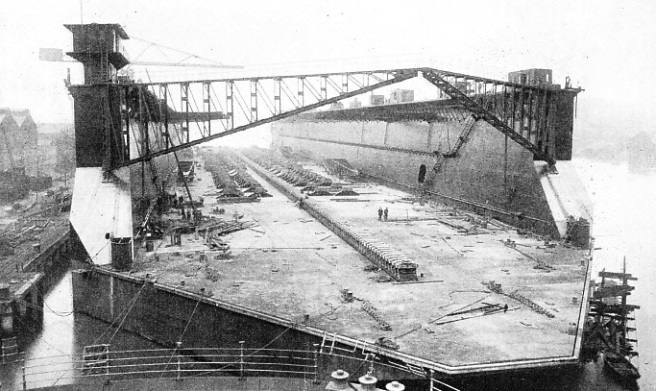
WORLD’S LARGEST FLOATING DOCK in the final stages of completion. Built in 1922 by Armstrong, Whitworth, for the Southern Railway, the Southampton floating dock has a lifting capacity of 60,000 tons. It is 960 feet long, with an overall width of 170 feet and a clear width inside of 130 ft 6 in. The total floor area of the dock is about 3½ acres.
IN recent years, ships have increased considerably in size. It has therefore been necessary to build larger docks in which the giant ships may undergo repairs. Of the two kinds of dock, the graving, or dry dock, and the floating dock, many people prefer the floating dock because it is more flexible.
A modern floating dock is nothing more than a huge trough-
Where there is a considerable difference between high tide level and low tide level, a small ship can be floated close inshore at high tide, and will then be left high and dry when the tide goes out. But in waters where the difference between the high and low tide levels is only slight, it is necessary, before repairs can be done to the submerged part of the hull, to find some artificial method of getting the ship clear of the water.
According to tradition, the earliest known form of floating dock was invented by an English sea-
This he gutted completely, removing the stern and fitting a water-
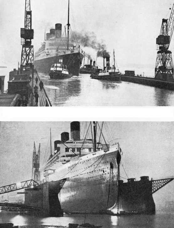
WHEN ENTERING THE FLOATING DOCK a liner needs the assistance of powerful tugs. The White Star liner Majestic, at one time the largest liner in the world, 56,599 tons gross, is entering the floating dock at Southampton for her annual overhaul. The Majestic was 915 ft 6 in long, with a beam of 100 ft 1 in and a depth of 58 ft 2 in. She was taken out of commission in February 1936.
TO RAISE A GIANT LINER above the level of the water the enormous dock can exert a maximum lift of 60,000 tons. In the lower picture the Majestic is shown docked at night in the world’s largest floating dock at Southampton. A large liner must be overhauled rapidly, and often more than 1,000 men work on her day and night while she is in the dock.
It is uncertain whether Watson used an old ship or whether he specially built his dock, but the principle of these early docks was the same. They were simply shells provided with a gate at one end, into which the vessel was warped; the gate was then closed and the water was pumped out of the confined pound. Their useful life was surprisingly long. Watson’s dock is known to have been in active use for forty-
The first improvement in the design of the floating dock was to make the walls and bottom hollow and thus buoyant. This gave two advantages. First, the heavy water-
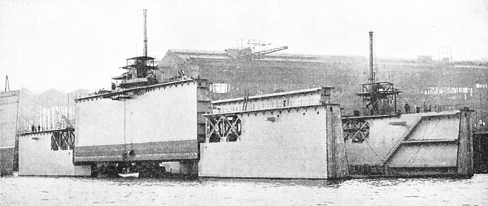
CLEANING AND REPAIRING A FLOATING DOCK. The side walls of this type are built in sections. The section to be cleaned is detached and the two adjacent sections of the dock are turned round and sunk. The outer sections are then drawn closer together so that when they are lifted again the centre section rests on the projecting ledges of the outer sections and is lifted above the water.
The shell was to be 220 feet long, 54 feet wide and 30 feet deep, with a large flange 6 feet wide extending outwards horizontally for the workmen to stand on and for additional strength. It was to be surrounded by semi-
The Americans were the first to put into practice a design for a hollow dock. They built their earlier docks of timber. The first of any note was that built for the Navy Yard at Portsmouth, New Hampshire, in 1848. Hollow-
So far, iron had not come into general use for the building of floating docks. Several designs for iron docks had been patented, notably one by James Taylor of Birkenhead in 1852. In this design the floor was divided into four separate compartments. Pipes from these compartments led to pumps separately controlled, the trim being maintained by further compartments in the side walls. But it was not until Edwin Clark, in the early 1850s, designed the hydraulic lift dock that iron began to be freely used.
The design was a departure from previous practice, since the rectangular iron pontoons of which the dock was formed depended for their lift, not upon pumps, but upon a range of hydraulic rams embedded in immensely heavy foundations at the bottom of the harbour.
The method of working was first to admit water to the pontoon so that it sank on to the ram heads, then to float the ship over it, lift pontoon and ship high enough to allow the water to run out of the pontoon, close the pontoon valves, and finally release the rams, leaving the pontoon floating with the ship on top of it. The disadvantages of the arrangement were the high initial cost and the relatively small capacity. The hydraulic gear had to be provided with foundations nearly equal in strength to those of a masonry or graving dock. Docks of this type -
The first Bermuda dock, built to the order of the Admiralty in 1868 for use by the West Indies Squadron, is an interesting example of a hollow-
SELF-
Most of the floating docks built up to this date were of the kind classified as box docks; that is to say, they were built all in one piece. This method of building gave rise to the quaint difficulty that the docks themselves could not be docked, being much too large to go into any masonry dock. In a landlocked bay or warm tropical waters, the deterioration or fouling of the underwater surfaces soon necessitates repair.
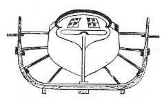
CHRISTOPHER WATSON’S DOCK was built at Rotherhithe on the Thames in 1785. This drawing, taken from a contemporary print, shows a stern view of the brig Mercury in the dock. The first floating dock in Great Britain was built in 1776.
In the Bermuda dock it was hoped that the U-
To get at the bottom, however, the dock had to be canted so far that there was grave danger of its capsizing. As this had nearly happened once at a trial in Portsmouth Harbour, no further attempt was made. Eventually the dock became so foul owing to the impossibility of cleaning, that it was decided to fill in the floor and part of the walls with concrete and to use the dock as an ordinary graving dock.
The difficulty experienced in cleaning the underwater surfaces of floating docks led to the introduction of the self-
The great disadvantage of these sectional docks was their lack of rigidity. The sections were joined together merely by lashings or timber-
Many accidents have been due to the end pontoon bodily slipping from under the vessel’s forefoot. In one instance, this almost caused the destruction of the dock, an old timber one. When the section slipped out, the extra weight thrown on the next section was sufficient to cause it to collapse, and the vessel then launched itself end-
A great improvement on the early sectional docks was introduced by the great engineer Bennie in his Cartagena Dock, built in 1859. In this form, classified as the sectional pontoon dock, only the pontoons forming the floor of the dock are in sections, the side walls being continuous. The side walls rest on the upper surfaces of the pontoons, to which they are attached by heavy fishplate joints, lugs and taper pins. In self-
Although the longitudinal rigidity of the sectional pontoon is vastly superior to that of the old sectional docks, yet it is not sufficient to obviate entirely the risk of accident. Since the pontoons are not connected in any way the whole resistance to bending must be taken by the walls alone. These docks have often had their decks buckled while lifting short and heavy vessels or they have been badly damaged through working in a seaway. In the summer of 1903 a dock of this type, of about 8,000 tons lifting capacity and 436 feet long, had its back almost broken through during a gale in the English Channel, and the pontoons were permanently altered in shape.
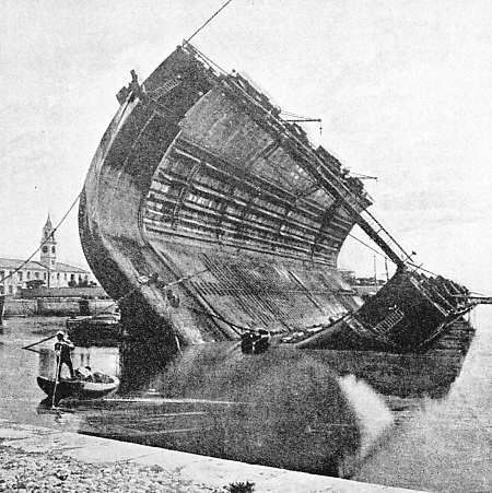
THE FIRST BERMUDA DOCK was a hollow-
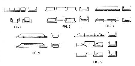
For many further improvements which have taken place in the design of floating docks during the last fifty years, Clark and Standfield, the Westminster firm of consulting engineers, have been almost entirely responsible. In 1895 they greatly increased the longitudinal strength of floating docks by their “Havana” design. In this type of dock the pontoons, besides being attached to the side walls, are themselves fastened together by means of fishplate joints. The depth of the walls is extended to the full depth of the pontoons, and the walls are attached, not to the upper, but to the outer surfaces of the pontoons (see Fig. 4, above).
For self-
Of this Havana type the best-
Rigid as the Havana type proved itself to be, the demand for a still more rigid form of dock has been made. This led Clark and Standfield to design the bolted sectional or sectional box dock. This is a reversion to the old type of sectional dock. The difference in the new type is that the sections are rigidly bolted together, thus forming a continuous trough-
Lifting Power of 60,000 Tons
In self-
When a terminal section (which is pointed) is lifted, the dock is divided into three and the pointed portion of one lifting section is passed under the square portion of the lifted section. The rectangular central section is then lowered and backed in, so that the pointed portion of the lifted section enters between its walls. This method of self-
The Southampton dock, built to this design by Armstrong, Whitworth for the Southern Railway, is the largest floating dock in the world. It has a lifting power of 60,000 tons. The length is 960 feet, the overall width 170 feet, the clear width inside 130 ft 6 in and the depth of the floor 20 feet. The draught over the keel blocks, with the top of the side walls 6 ft 6 in out of the water, is 38 feet.
The complete weight, including fittings and machinery, comes to about 19,000 tons. The total area of the floor is about 3½ acres. Some 3¼ million rivets have been put into the dock, and approximately 7½ million rivet holes have been either drilled or punched. The dock is in seven sections and each section is provided with its own pumping machinery. A centrifugal pump at the bottom of the dock, operated through vertical shafting by an electric motor situated in a house on the top deck, is installed on either side of each section, so that there are fourteen main pumps and as many motors.
The control of these various units is completely centralized. The valves and pumping motors are operated electrically by means of a push-
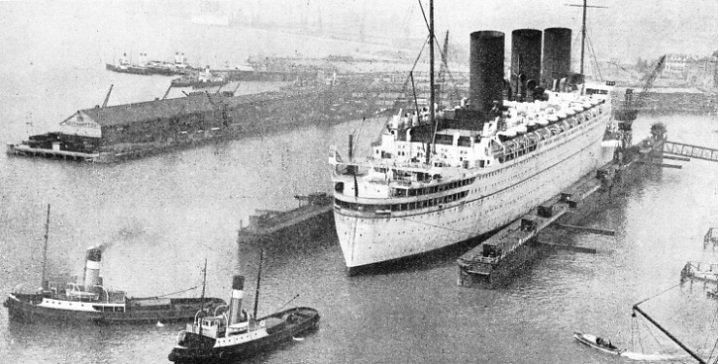
TOWING OUT OF A FLOATING DOCK. Southampton saw the world’s largest liners in the world’s largest floating dock before the advent of the new graving dock. Above is the Empress of Britain, a famous Canadian Pacific quadruple-
The various apparatus for the control of the dock is installed on two tables, about twenty feet long, placed in the valve-
An electrical device indicates with lamps when the ship’s keel lies centrally on the keel blocks, and similar devices installed in the valve-
There is thus concentrated in the valve-
At the official trial, this dock lifted the Olympic, of 46,439 tons gross, in three hours fifty-
Interesting developments of the floating dock are the “off-
The depositing dock was developed by Clark and Standfield in 1876 for the purpose of docking Admiral Popoff’s circular ironclads in the Black Sea. These vessels, one of which is illustrated in the chapter “Novelties in Ship Design”, were so wide that no conventional dock could accommodate them. The dock consists of a series of long hollow fingers connected to a hollow wall. Along the shore a staging or gridiron was built, the spacing between the grids corresponding with the spacing between the fingers of the dock.
The method of working was to lift the ship in the usual way, tow the dock with the ship in it sideways to the staging so that the fingers of the dock and the grids of the staging interlaced, and then to sink and withdraw the dock, leaving the ship deposited on the staging.
Floating Dock’s Mobility
The advantage was that, besides accommodating ships of unusual width, the same dock could be used to deposit any number of ships on further lengths of staging. Examples of these depositing docks are still to be found at Nikolayev and Vladivostok, in Russia, at Barcelona, in Spain, and at Kobe, in Japan. The dock at Kobe was built chiefly for the purpose of dealing with gigantic monoliths of reinforced concrete, weighing up to 6,000 tons, of which the quay wall was being built.
One of the most valuable characteristics of the modern floating dock is its mobility. It can be built at the cheapest place and moved to the scene of its intended operation. The earlier docks were shipped out in pieces and the final assembly was done on the spot. L. Smit and Company’s Internationale Sleepdienst, of Rotterdam, has the greatest number of these passages to its credit.
Its tug Zwarte Zee, 793 tons gross, is one of the most powerful tugs in the world.
The towing gear generally used is extra superior Manila rope of 18 to 20 in circumference, with a bridle of 6-
During the voyage of the Durban dock in 1903, bad weather encountered in the South Atlantic made towing impossible for two days, and the dock drifted for eighty miles before the tugs could attempt to take it in hand again.
The largest dock ever towed a long distance is the 50,000-
The longest tow of this kind was that performed by the tugs Zwarte Zee and Witte Zee in 1931, when they took a 17,000-
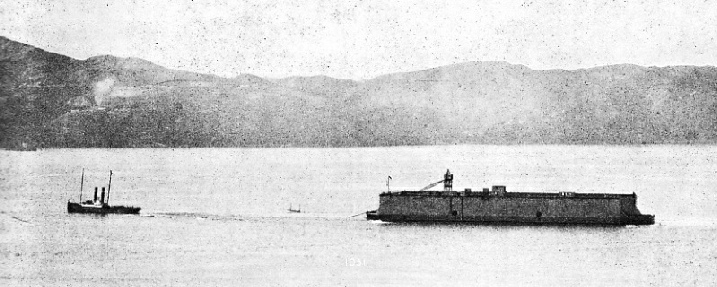
END OF A 12,000-
You can read more on “Southampton”, “Wellington” and “The World’s Largest Ships” on this website.
You can read about “The World’s Largest Graving Dock” in Wonders of World Engineering